LocksleyFox
A home-built, fox-styled quadruped with RobStride actuators, 3D-printed legs and sim-first design.
Description
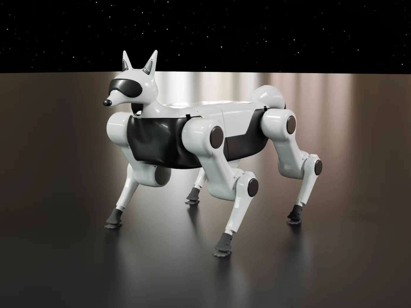
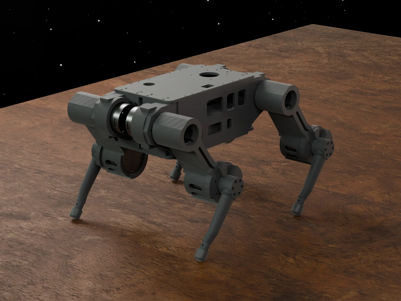
LocksleyFox is a four-legged robot I'm designing and building at home. The goal is the kind of movement you usually only see from commercial robot dogs: a quick trot, jumps, and eventually flips, on hardware I can open up and program at the low level (including things like servo control).
It started because I wanted to buy a robot dog. Many years ago I fell in love with the idea of buying a Sony Aibo, but after learning how slow it moves I lost interest to a certain degree. But after seeing dogs that can do things like flips and climb stairs I discovered a new infatuation.
The robot dogs that do dynamic tricks either cost a lot or lock down low-level control, and the open ones are mostly small servo kits. The exception is ones that have good hardware and programmability, but those can easily exceed $10k. So I decided to build my own, one step at a time, instead of committing to a full build up front.
Also, it's hard to budget several thousand dollars for an expensive toy (like a Go2 Air) that I get tired of in a few weeks. By building it myself, I will be able to get better use of my time since I will be learning as I go, and get more satisfaction along the way. I can easily see this project taking a half a year, or longer.
It's a fox instead of a dog because there aren't many robot foxes out there. The plan is ears, a tail and a fox-like look on top of a fairly standard quadruped layout. But since I am focusing on the functional and mechanical aspects first, I haven't done the fox styling.
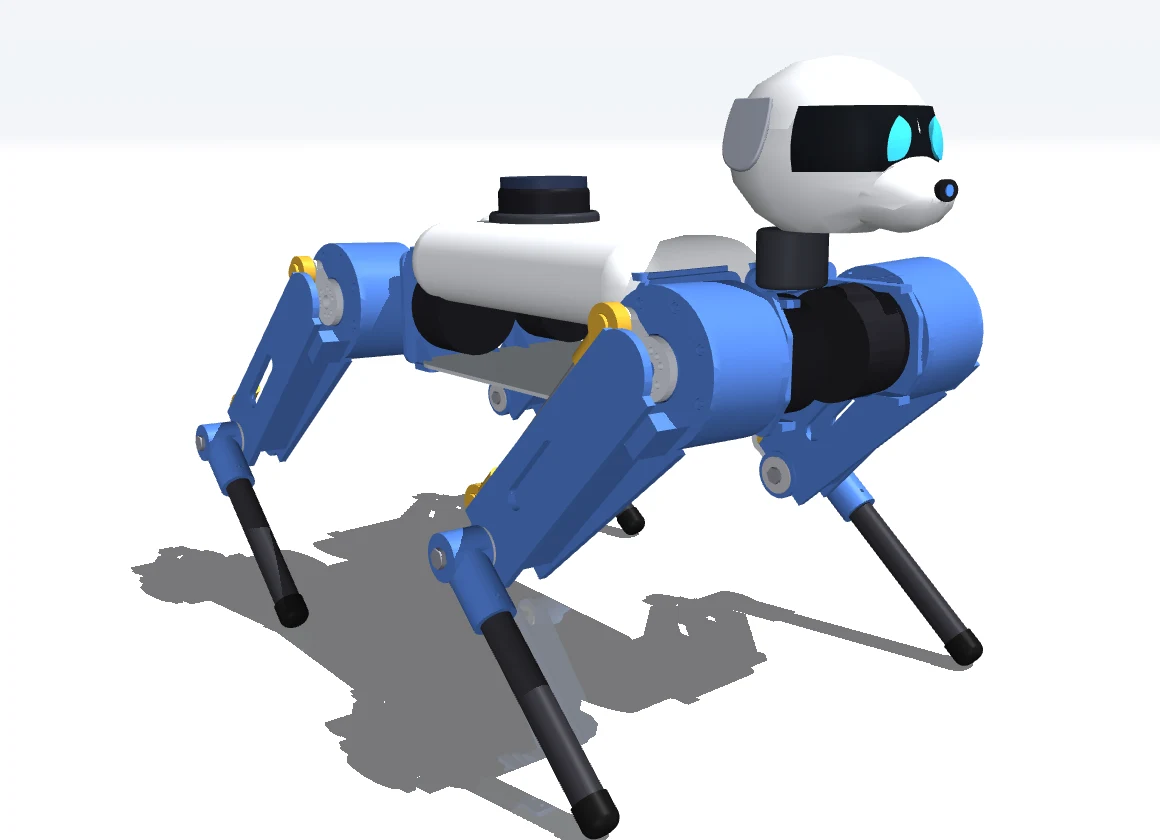
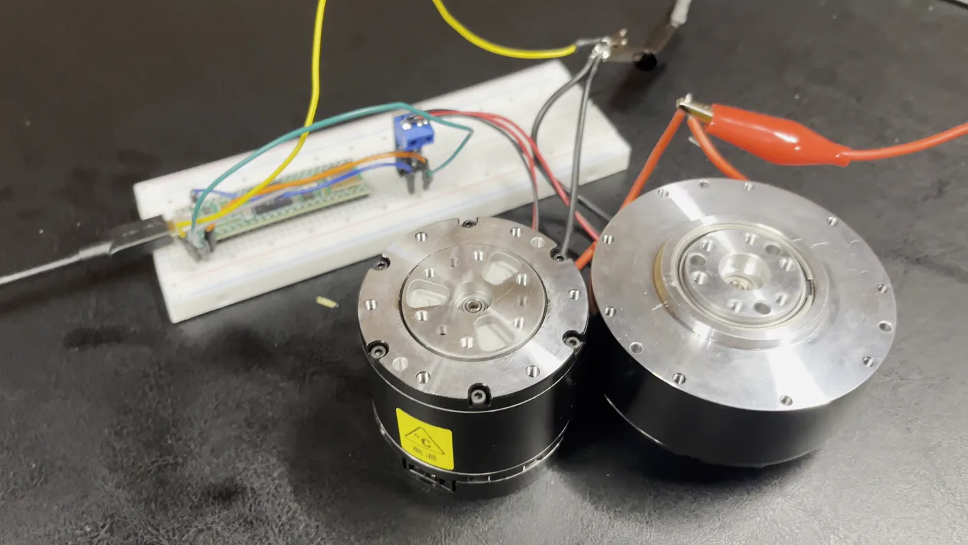
So far I have two motors running over CAN on the bench and the first leg printed for a fit check. Every design is tested in simulation before anything gets printed, and this page will log both the simulation results and the actual physical parts as they come together.
I'll be upfront from the beginning: I am using Claude for much of the design, building, and testing process. While I do have a formal education in Computer and Electrical Engineering (and a bit of robotics), I lack strong knowledge of things on the mechanical side like torque, materials, analyzing the strength of structures, etc. Despite the flaws of Claude (and other LLM-based tools), if you learn to work around the quirks you can achieve amazing jumps in productivity. I am not just following blindly what Claude suggests, but rather asking many questions and pushing through design iterations to get something better than whatever Claude randomly started with (for example when doing the leg design).
For the time being, the point of this page is to capture the process of designing, building, and testing the robot. Hence I won't be providing exact, finalized plans to build it. However, once I get it working well enough I am considering sharing the full designs so others can build the robot.
Details
Actuators
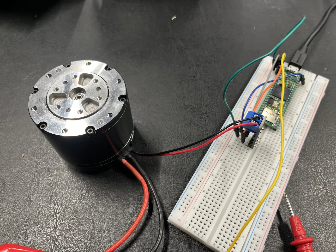
The legs use RobStride RS00 brushless actuators driven over CAN at 1 Mbps. I also tested the stronger RS02 on the bench, and a speed run on the RS00 held 315 rpm at 48 V.
Leg designs
I've gone through five leg layouts in simulation:
- 1.0: both motors at the hip, with a push rod down the thigh driving the knee (like the rods on a steam train). Light lower leg, but 21 parts per leg.
- 1.0b: knee motor (RS02) moved down to the knee.
- 1.0c: RS00 motors at both hip and knee, the knee motor turning the shank directly. 10 parts per leg, no linkage.
- 1.0d: 1.0c plus a soft ankle at the foot.
- 1.0e: a leaner 1.0d with a printed shank, vents for the knee motor and TPU foot pads. This is the one I've printed first.
In simulation with a realistic body (about 7.2 kg), 1.0c tops out around 1.4 m/s and 1.0d around 1.6 m/s, and 1.0d gets from standing to 1 m/s in about a third of a second. Both still walk carrying an extra kilogram. The limit so far is heat in the knee motor, which is what the next bench test will measure.
How each design is checked
- CAD written in Python, checked for part clashes and joint range
- Walking, jumping and flips trained with reinforcement learning in MuJoCo, using the motors' real torque and speed limits and a heat model
- Stress checks on the printed parts, modeled with the actual wall count and infill, not solid plastic
- Motor tests on the bench before anything goes on the robot
I wrote up the whole process here: Quadruped Design Validation
Electronics
A Teensy 4.1 talks to the motors through a Waveshare SN65HVD230 CAN board. A Raspberry Pi or Jetson will run the higher-level control later.
Printing
Parts are printed on a QIDI Plus 5. PLA for fit checks so far, and TPU for the foot pads.
Project logs
Log 1: Choosing motors and the first parts order (October 17, 2026)
I didn't want to spend thousands of dollars before knowing whether the motors would do what I needed, so the first order was only enough to test them: one RobStride RS00, one RS02, a Teensy 4.1, CAN boards, and the basic tools I didn't own yet (soldering iron, wire cutters and so on). About 30 items and around $900.
I bought one of each size on purpose. The RS02 is the stronger one I expected to need at the knee, and the RS00 is the lighter one for the hip. Having both on the bench meant I could measure them before deciding how many of each the full robot needs.
Log 2: First motors spinning over CAN (October 22, 2026)
Getting the first reply from a motor took three nights.
Night 1: a USB-to-CAN adapter straight from the Mac. The bus flooded and the motor never answered. I assumed the motor was the problem.
Night 2: a Teensy 4.1 with cheap SN65HVD230 transceiver boards. All three boards failed the same way. When they were supposed to drive the bus, both CAN lines dropped to about 0 V, even on a board that had never been near the motor. It seems to have been a bad batch.
Night 3: a genuine Waveshare SN65HVD230 board. It passed the line test right away, and the RS02 answered on the first ping. It was the same motor from night 1, so the motor had been fine all along. After that it was quick: a 45° move, then the RS00 on the same bus, a full turn, and a speed run that held 315 rpm.
Lesson: test the transceiver on its own first. If it can't pull the lines apart when driving, nothing else matters.
Log 3: Leg 1.0 and the first printed leg (October 27, 2026)
Leg 1.0 keeps both motors at the hip and drives the knee with a push rod, so the lower leg stays light.
Since then the design has moved to the knee motor sitting at the knee (1.0c to 1.0e), which cuts the parts per leg from 21 to 10. The first printed parts are a fit check of 1.0e in gray PLA: the thigh with the knee-motor housing and vents, and the shank with its end-stop tab.
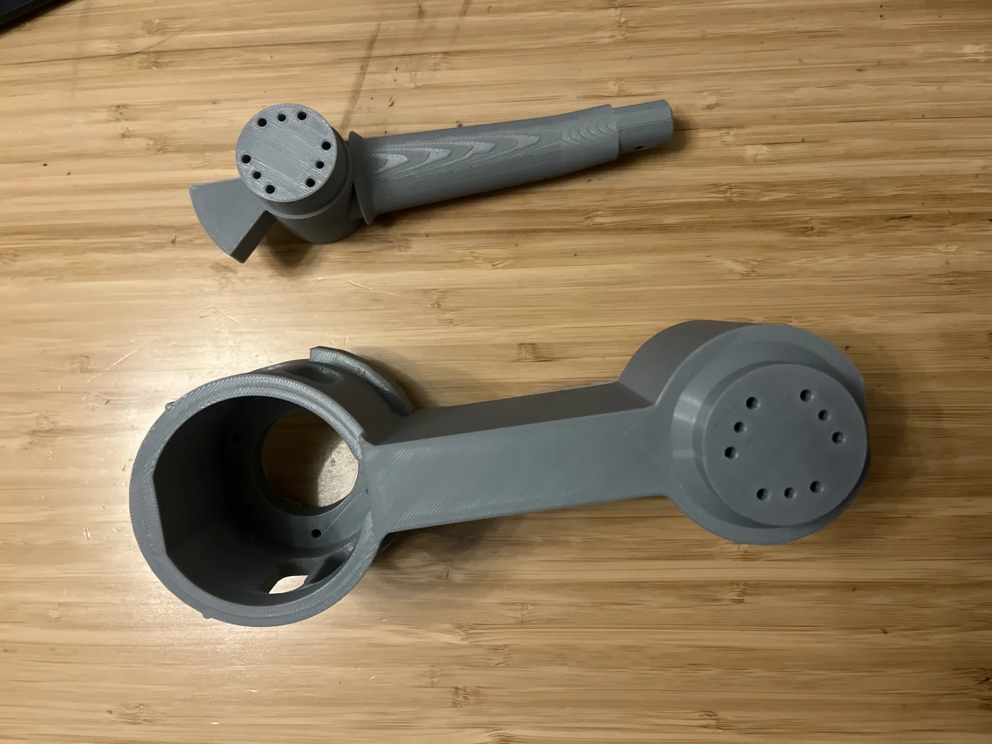
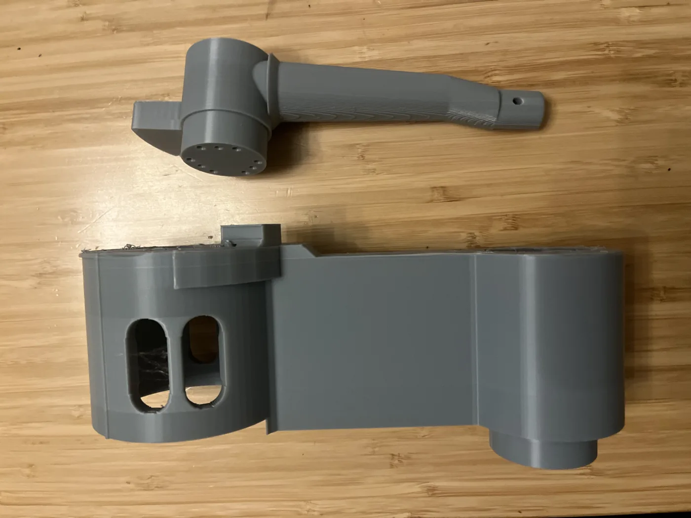
Not everything printed the first time. The hip mount failed partway through when two tall, thin tree-support trunks came loose from the bed. The fix was sturdier tree supports, wider branches and a raft that merges the support feet into one large base.
Next up: the torque test on the motor stand, then a heat test on the knee motor, which simulation says is the part most likely to run hot.
Log 4: Torque test on the motor stand (October 27, 2026)
On an earlier bench night I told the RS00 to produce a set torque, but its own sensor reported only about half that while the motor was turning. If the motor really delivers only half, the inertia I measured that night is wrong, and so is every torque the simulation assumes. The only way to settle it was to measure the torque from outside the motor.
The RS00 sits in a printed stand with a 300 mm lever on its output. A strap runs from the lever's 200 mm hole to a luggage scale, and a cord ties the scale to the table. The motor holds six torque steps from 0.5 to 5 N·m. The scale reading times the 200 mm arm gives the real torque.
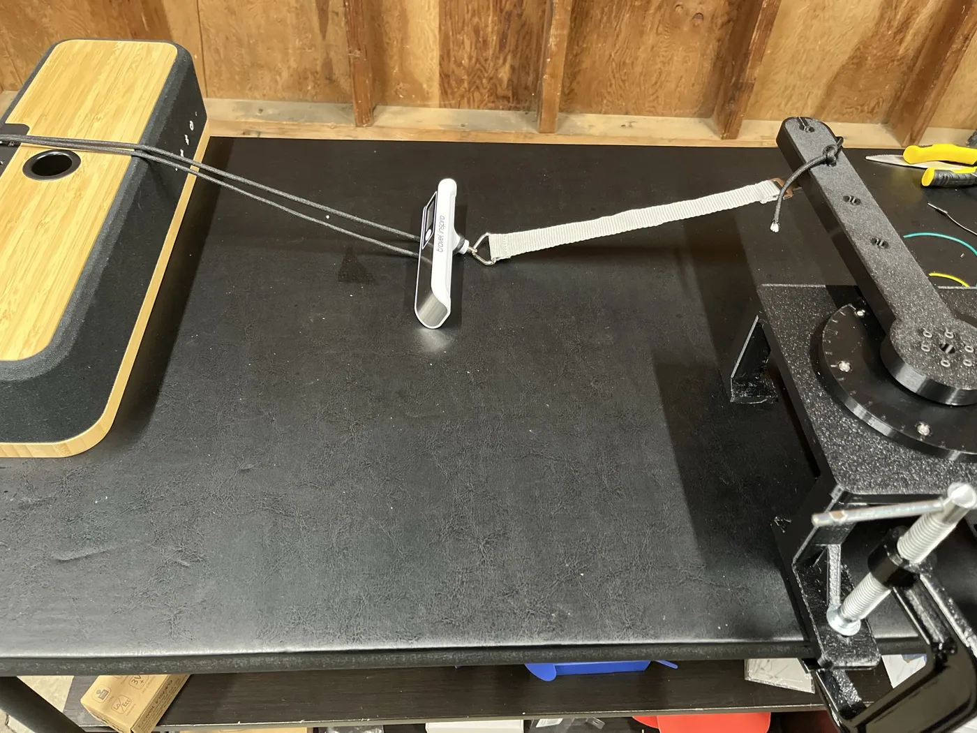
It took five runs to get a clean one. The scale freezes its reading after each pull, and the first holds were too short to read and reset it. A slack cord then let the lever swing far enough to trip the safety stop. Longer holds, a tighter cord and spoken cues from the Mac ("pulling", "read now", "reset the scale") fixed both.
From 3 to 5 N·m the motor delivered 89 to 95% of the command. Across all the steps it works out to about 98% of the command minus a fixed 0.35 N·m. That fixed loss is most likely gearbox friction while the output is held still. The readings repeated within one scale count between runs.
So the motor does what it's told. The low reading while turning was never a fault in the sensor or the motor. It comes from how a motor behaves while it speeds up. Part of its torque goes into spinning up its own rotor and gears, and only the rest reaches whatever is attached. As far as I can tell from the logs, the RS00's reading reports that remaining part, the load on the output. With only friction attached, that came to about half the command. While the motor slows down the reading even flips sign, because friction always pushes against the motion. Holding still, nothing is speeding up, so the reading and the real torque match, as they did in this test. It also means the inertia from the earlier test stands, about 0.022 kg·m² at the output, four times what the simulation was using. The simulation gets that update next, and then comes the heat test on the knee motor.
All in all, this was a good science experiment, and I learned a little bit about physics along the way. Exercises like this are really helpful for me to gradually improve my knowledge about mechanical stuff that I really haven't studied much until now.
Log 5: Heat test on the knee motor (October 28, 2026)
In simulation, the thing that limits speed and payload has always been heat in the knee motor, an RS00. The simulation's heat model starts from RobStride's tables for a motor bolted to a metal heat sink. For a knee motor inside the robot, the simulation assumes it sheds heat less well, but that part is only an estimate. Nobody seems to publish real thermal data for these motors, so the only way to check that guess was to heat one up.
The setup reuses the stand from the torque test. This time a steel extension spring hooks onto the lever's 200 mm hole, and a cord holds its far end. The motor pulls against the spring with a steady torque plus a small wobble twice a second, a bit like a knee holding the robot up while it walks. The Mac logs the motor's own temperature sensor, and the test stops itself at 100 °C.
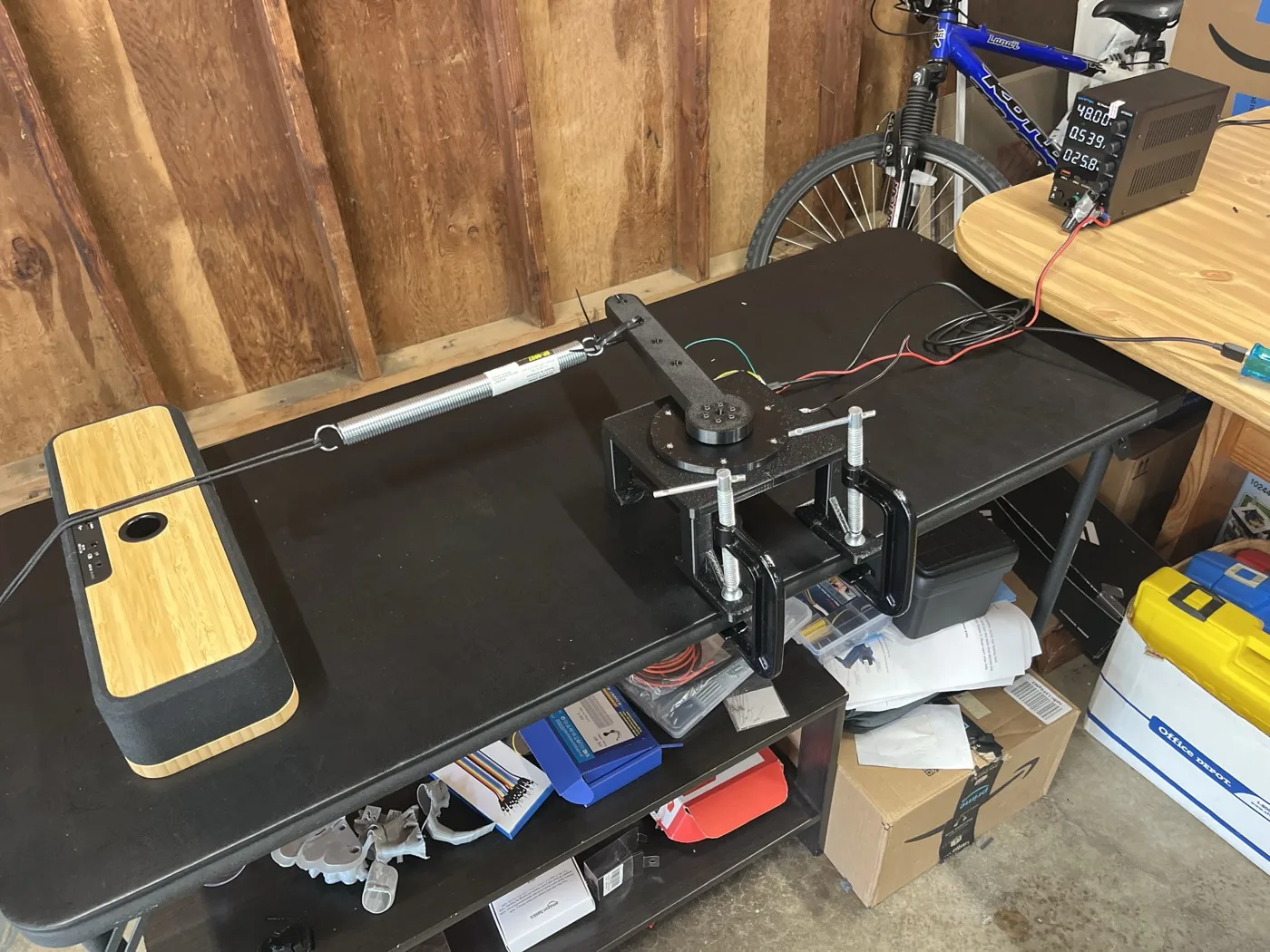
The first direction check moved the lever only half as far as expected. A photo of the rig showed why. The towel I'd put down as a soft stop was on the wrong side of the lever and was holding it back. With the towel moved, the lever swung the expected 3°.
The main run asked for 4.2 N·m, about 85% of the motor's rated torque. The motor went from 17 °C to 100 °C in just over nine minutes, and it was still climbing when the cutoff stopped it. The power supply showed something interesting along the way. It drew about 22 W at the start and 28 W near the end for the same torque. Copper's resistance rises as it heats up, so the hotter the windings get, the more power turns into heat.
After the run the printed stand around the motor was still cool to the touch, and only the lever's hub was a little warm. Most of the heat leaves through the motor's own case into the air. Fitting the heating and cooling curves gives the motor's thermal resistance, how many degrees it rises above the room for each watt of heat. It came out at roughly 4 to 5 °C per watt. That's close to RobStride's own heat-sink setup. But this was the bare motor in open air. Inside the robot the knee motor sits in a mostly closed printed housing with a few vents, which will trap heat. I haven't tested that yet. The simulation's figure for the housing comes from a calculation, and it lands at roughly 5.5 to 9 °C per watt, depending on the vents and airflow. Testing the motor inside a printed thigh is the next step after this one.
One run isn't enough to trust that number. The motor never levelled off, so the fit had to guess where it would have settled. The next run uses a lower torque, 3 N·m for 45 minutes, which should give the temperature time to settle on its own.
Log 6: Heat test, part two: the knee housing (October 29, 2026)
Log 5 left two questions open. The first run never levelled off, so its number was partly a guess. And it tested the bare motor in open air, while in the robot the knee motor sits inside the thigh, wrapped by a printed wall.
The same evening I ran the longer test, at 2.4 N·m for an hour. I dropped the torque from the planned 3 N·m so it would match the housing test. Starting from 14 °C, the motor climbed for 45 minutes and peaked at 89 °C. My model had predicted around 40 °C. Near the end I opened the garage door a few times, and the draught pulled it back down to 81 °C.
Why so much hotter? The model only counted the heat from current flowing through the copper windings. So I held a few torques for a couple of minutes each and read the watts on the power supply. Holding still, the motor does no mechanical work, so every watt it draws ends up as heat inside it. At 2.4 N·m it drew 9.3 W, about twice what the copper alone explains. Even holding almost nothing it used about 3 W. Some of that is the motor's built-in driver electronics. Counting the real watts, the bare motor on the stand rises about 7.5 °C per watt, more than the 4 to 5 from Log 5.
For the housing test I printed a new version of the stand's adapter in PETG with the knee wall from leg 1.0e. It has a 6 mm wall, a 1.5 mm air gap around the motor and four vent windows. Everything else stayed the same: the lever, the spring and the cord.
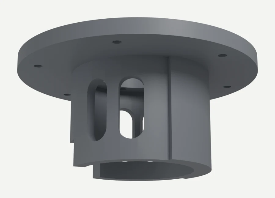
The bare motor already reached about 90 °C at 2.4 N·m, so this run used 1.5 N·m. I also added a 75 °C cutoff, because PETG starts to soften not far above that. From 14 °C the motor rose to 41 °C and levelled off after 47 minutes. The supply read a steady 4.5 W the whole time. Afterwards the motor case was a little warm, the plate and lever hub less so, and there was no smell and no warping.
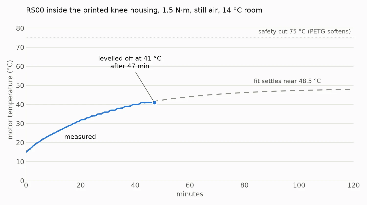
That works out to about 7.7 °C per watt, against 7.5 for the bare motor. Fitting all three runs together puts the housing somewhere between no worse and 20% worse. The plastic isn't acting as a heat sink, since PETG barely conducts heat. The vents and the air gap simply let the heat out about as well as open air does.
Then I put the measured numbers into the simulation's heat model. They pull in two directions. Over a long time the motor runs hotter than the old guess, but the motor and the plastic around it soak up more heat first, so it takes longer to get there. In still air, the knee can hold about 2.6 N·m forever before the windings reach their 145 °C limit. Walking in the simulation needs more than that at the knee, so no walking speed can go on forever. The table shows how long each leg design walks from a cold start before the knee needs a rest.
| Leg and speed | Knee load | Old estimate | Measured housing |
|---|---|---|---|
| 1.0c, 0.5 m/s | 4.0 N·m | 9 min | 20 min |
| 1.0c, 1.0 m/s | 4.2 N·m | 6 min | 17 min |
| 1.0c, 1.5 m/s | 4.8 N·m | 4 min | 12 min |
| 1.0d (soft ankle), 0.5 m/s | 3.3 N·m | no limit (levels off at 122 °C) | 36 min |
| 1.0d (soft ankle), 1.0 m/s | 3.7 N·m | 12 min | 24 min |
| 1.0d (soft ankle), 1.5 m/s | 4.4 N·m | 5 min | 15 min |
Times are from a cold start in still air at 25 °C, until the windings reach 145 °C. The current design, 1.0e, is 1.0d with lighter parts, so it should do about as well as the 1.0d rows or slightly better.
All of this is still air. A walking robot moves air over its legs, which can only help. The next run is the same test with a fan blowing on the motor.
Log 7: The whole leg on the bench (October 31, 2026)
Up to now each motor had been tested alone on a stand. This is the first time the full leg came together: the hip motor in its printed mount, the knee motor inside the printed thigh, and the shank and foot below it. Everything is still the gray PLA fit-check print of leg 1.0e.
The night before, I put the knee motor into the thigh on its own and found its range by hand. With the shank against its end stop the motor reads 2.721 rad, and the design allows 120° of bend from there. Then came the first powered knee moves: 30°, 73° and 113°, each slow, held for two seconds and brought back. After that, a smooth back-and-forth sweep up to 4 rad/s. No faults, and the motor stayed at 15 °C.
For the full leg I clamped a board to the workbench and hung the hip mount underneath it, so the leg swings freely in the air with nothing to hit. Both motors share one CAN bus from the Teensy.
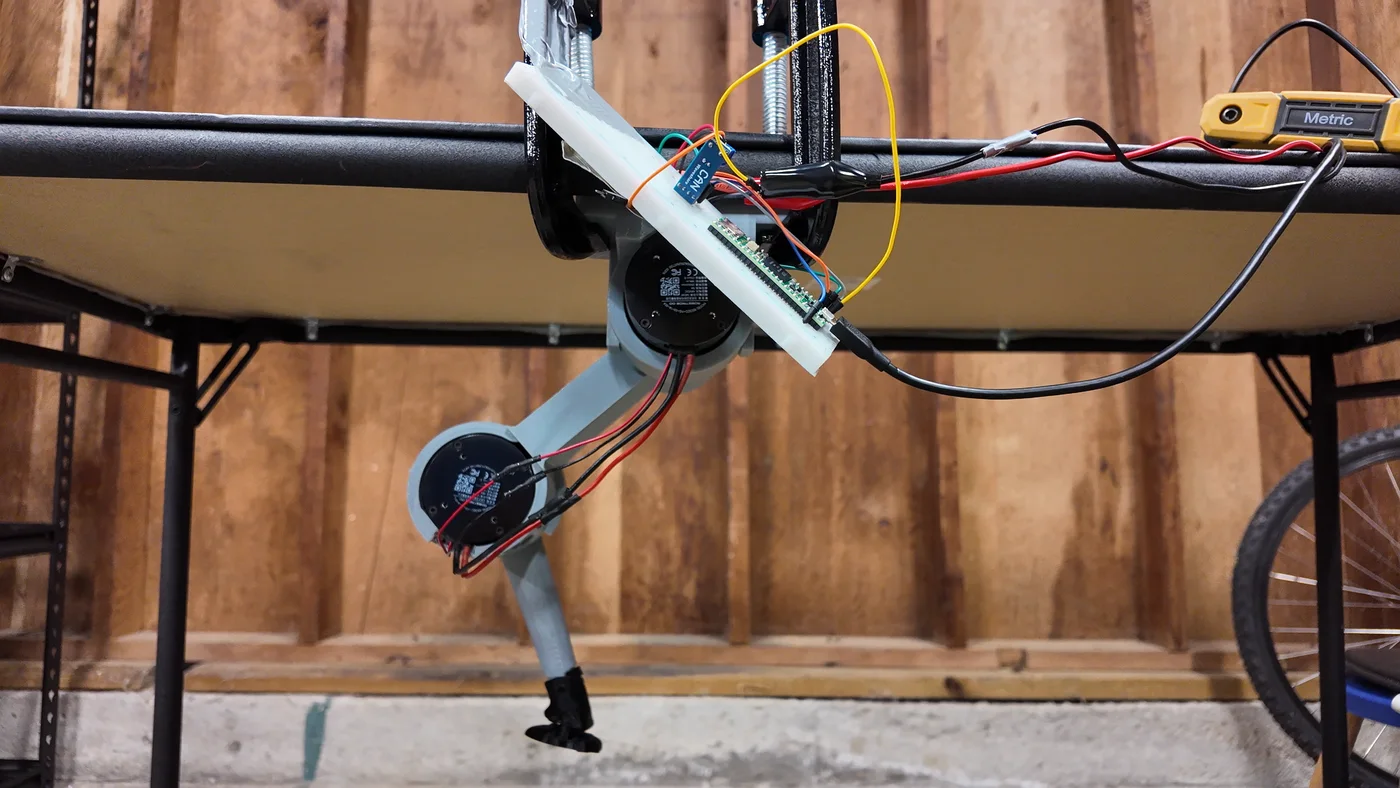
The first scan only found the new hip motor, still on its factory ID of 127. The knee motor didn't answer at all. The cause was the plug between the two motors, which wasn't fully seated. After re-seating it both answered, and I gave them their permanent IDs, 1 for the hip and 2 for the knee. They kept them after a power cycle.
Then the first moves with the whole leg: the hip alone lifting the thigh 30° and back, then both motors at once. After that I wrote a simple walking motion, with the hip swinging back and forth while the knee lifts the foot on each forward swing. It ran four times for the camera, speeding up to one stride a second, with no faults and both motors at 20 °C.
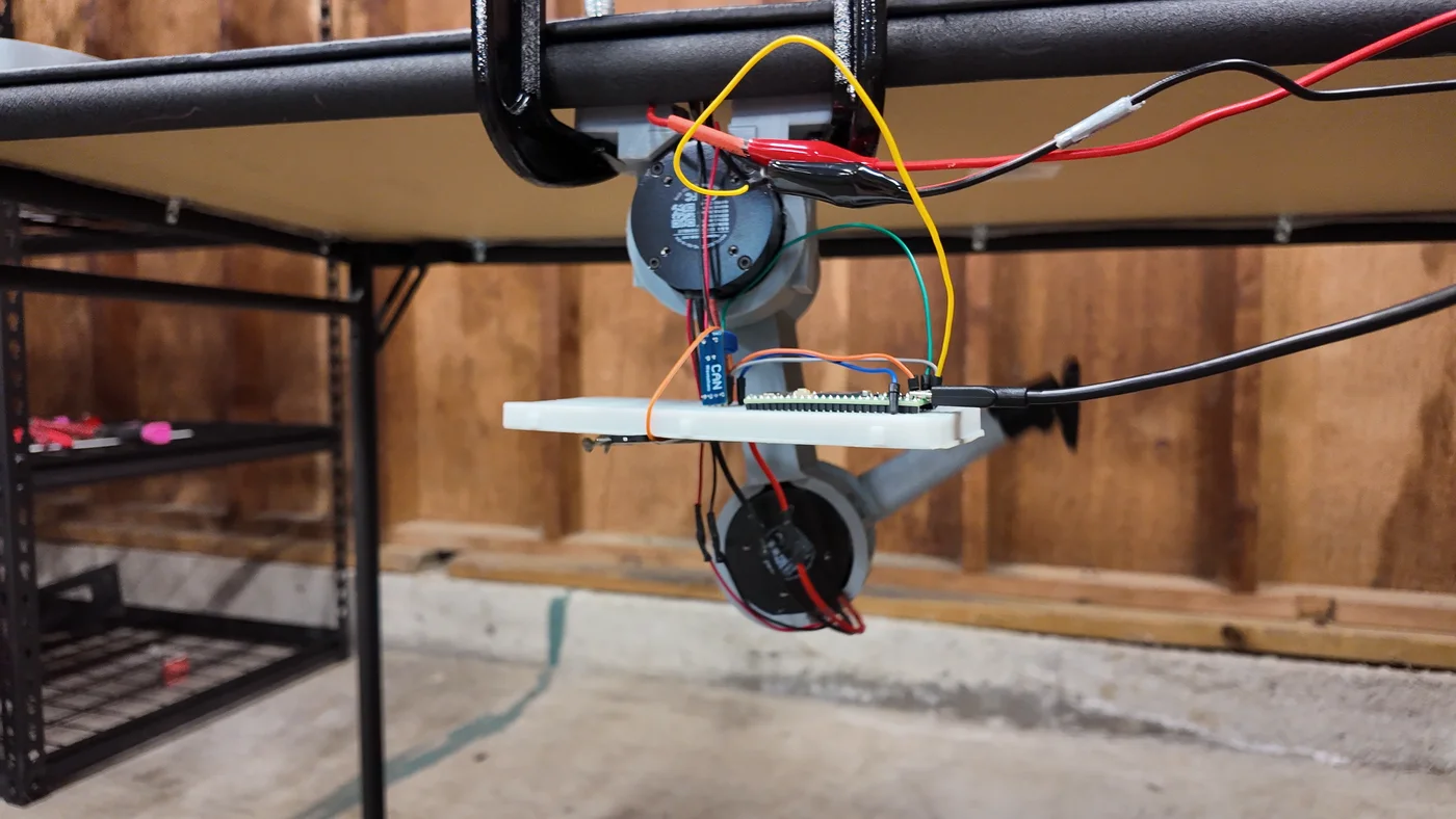
Watching the video afterwards, it didn't look like walking. The hip went out to one side and straight back, and the knee folded most at the far end of that swing. I fixed the timing, but the evening video was still wrong in a different way. The thigh hung straight down and the knee stayed bent, so the shank stuck out sideways. The foot never came under the hip or anywhere near where the ground would be.
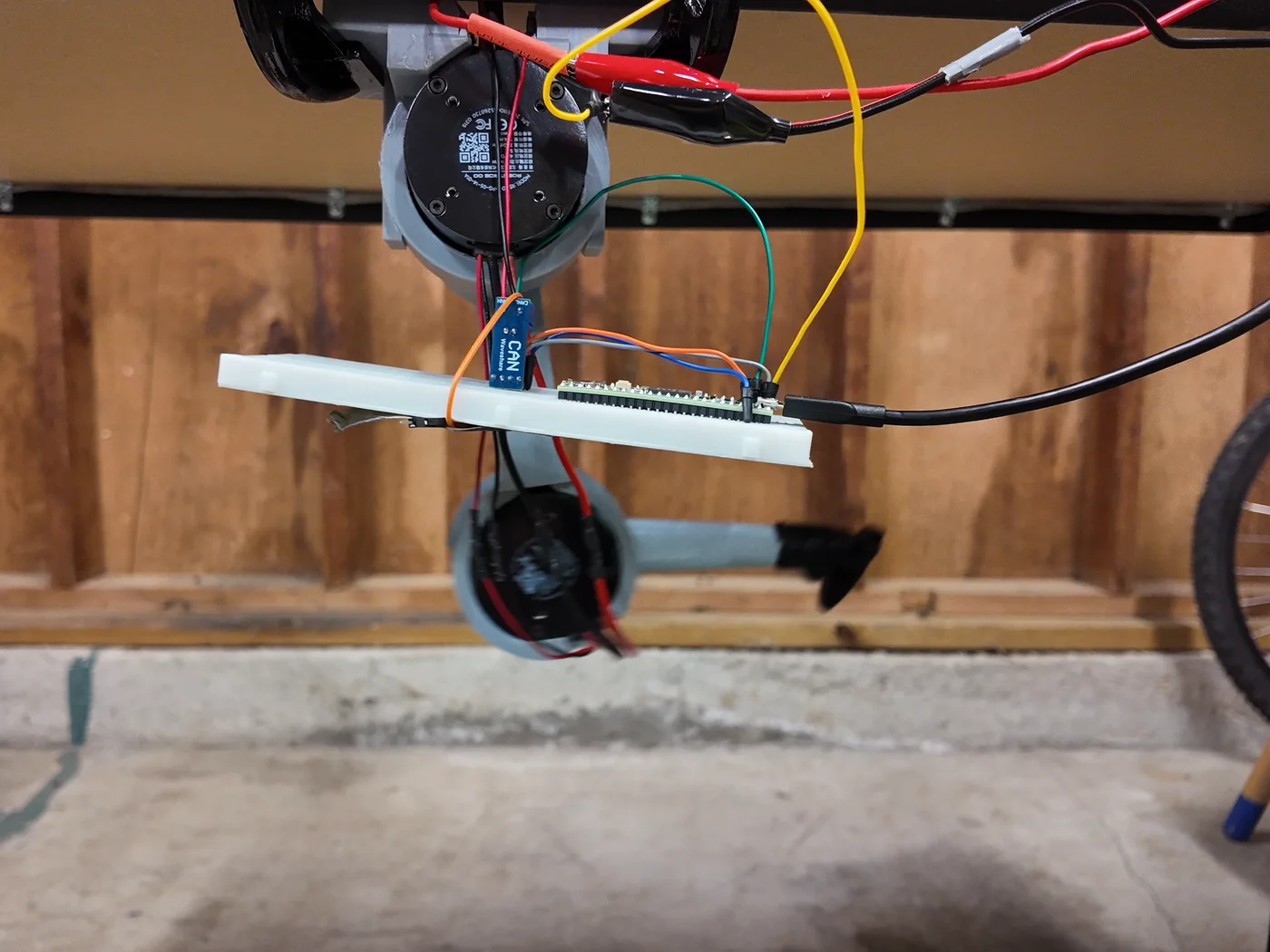
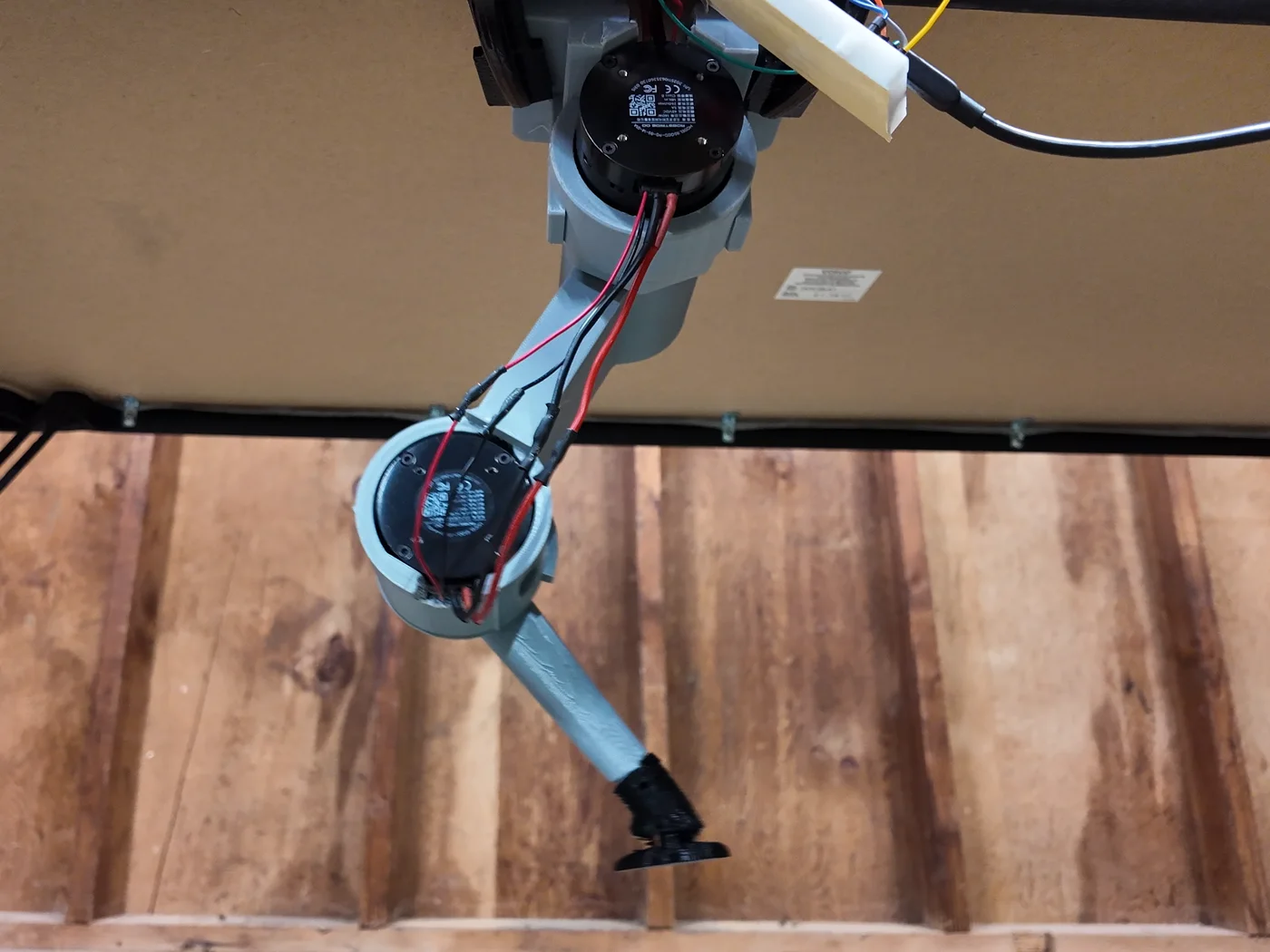
The real problem was the approach. I had been moving each joint on its own and hoping the foot ended up in the right place. The fix was to plan the foot instead. In stance, the part of the step where the foot is on the ground, the foot slides straight back along a flat line 224 mm below the hip. That's the standing height from the simulation. In swing it lifts and comes forward. The Teensy turns each foot position into hip and knee angles 100 times a second using the leg's geometry (two 140 mm links). This is called inverse kinematics.
Before running it, I checked the geometry with a still pose. Both joints moved to the standing position and held it. The front tip of the foot ended up right below the hip motor, with the foot pad almost flat, tipped down only 2 or 3 degrees at the toe. So the leg matches its own math closely.
The first planned gait used a short 40 mm step, because I had guessed the hip's range too small. I moved the leg by hand to show how far back the hip can really go, and with the corrected limit the step grew to 80 mm with a 40 mm lift. Then I ramped it from a quarter stride a second up to 1.58 strides a second. That's about twice the earlier speed, and as fast as the knee can go under the software's 6 rad/s safety cap.
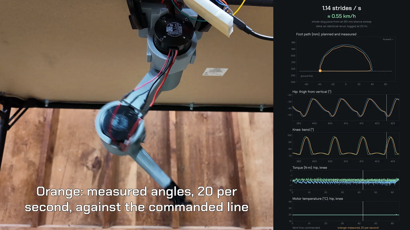
I ran it a second time with logging at 20 samples a second, so the graphs show real measurements:
- The measured foot path sits right on the planned one. At slow speed the foot was within about 4 mm of the plan on average. At top speed it trailed by up to about 17 mm, cutting the top of the swing a little short.
- Torque stayed small, about 1.2 N·m at the hip and 0.5 N·m at the knee. That's under 10% of what the motors can do, since the leg is only moving its own weight.
- Both motors stayed at 19 °C the whole time.
How fast would that be for a whole dog? Each foot pushes 80 mm back while it's on the ground, which is 60% of each stride. At 1.58 strides a second, four legs like this would carry the body at about 0.21 m/s, or 0.76 km/h. That's a slow walk. The limit is the cautious speed cap, and the motors have plenty left.
One recurring annoyance: the Teensy has dropped off USB five times so far. Re-seating the cable and pressing its program button brought it back each time. The cable or the connector is the next thing to replace.
Log 8: Checks before printing more legs (October 31, 2026)
With one leg working, the next step is printing three more and switching from PLA to PAHT-CF, a stronger nylon filled with carbon fiber. Before spending that time and filament, I wanted to prove as much of the design as I can with this one leg. So I made a list of checks, ordered from safest to riskiest, and started working through it the same night.
| Check | What it shows | Result |
|---|---|---|
| 0. Walking gait | The leg can follow a planned foot path | Pass (Log 7) |
| 1. Zero after power cycles | The joint angles stay right after the power is cut, so no homing step is needed | Pass |
| 2. Full-range sweep | The cables don't pull, pinch or rub anywhere in the range | Pass |
| 3. Gravity hold | The leg's mass, its balance point and the motor's torque reading all match the model | Pass |
| 4. Free swing | Inertia and friction at the hip match the simulation | Pass |
| 5. Endurance | 30 to 40 minutes of walking, then a check for loose bolts, wear and heat | Next |
| 6. Foot press | The foot pushing down on a bathroom scale matches the force the motor torques predict | Next |
Zero after power cycles
The motors measure their output angle with a built-in sensor. If that reading drifted every time the power came back on, all the joint limits I measured by hand would be wrong after a restart, and the robot would need a homing routine. So I switched the supply off and on five times without touching the leg. The Mac read both angles three seconds after each restart and spoke a cue for the next one. The hip read 0.639 rad and the knee 2.700 rad every single time. The spread was zero, finer than the sensor's own steps of about 0.02°.
Full-range sweep
Each joint moved slowly to both ends of its range and held there, and then both joints went to all four corner combinations together. At every position I watched the cables at the thigh slot and around the hip. Nothing pulled, pinched or rubbed. This only covers the range I can reach on this rig, though. The simulation uses a wider hip range, so the cable routing needs another look before the robot uses all of it.
Gravity hold
The hip motor held the leg at six angles from 60° back to 35° forward, approaching each angle once from below and once from above, while the Teensy averaged the motor's own torque reading. Holding still, all of that torque is just the weight of the leg pulling down. I compared it with what the CAD model says the printed parts weigh and where their balance point is. The measured torque came out at 0.934 times the model, within 7%. The gap between approaching from below and from above shows about 0.05 N·m of friction.
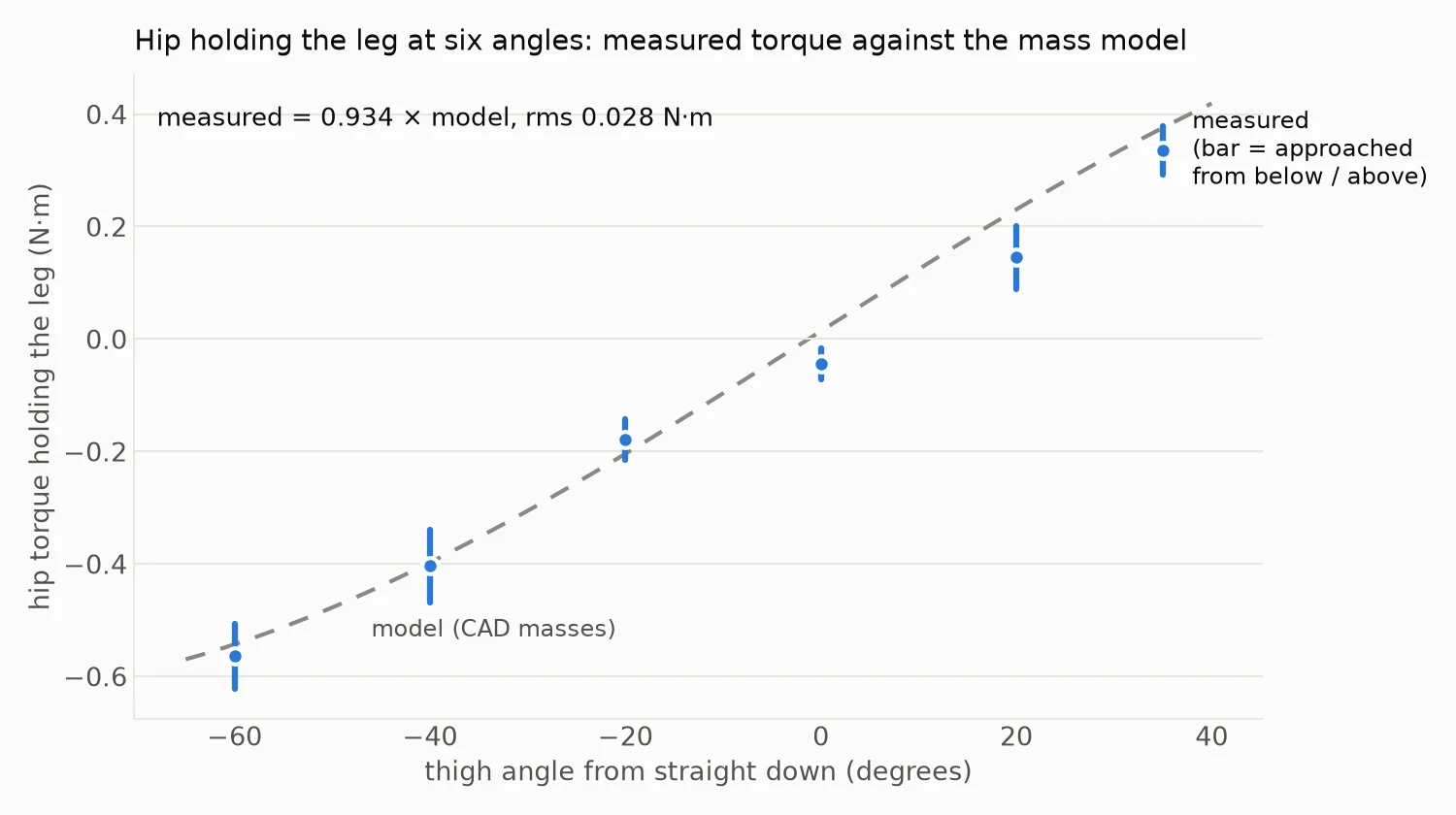
That confirms two things at once. My method for working out each part's mass from the slicer settings works. And the motor's torque reading can be trusted even at these small loads, about 4% of its maximum.
Free swing
This one took a few tries. The idea was to lift the leg, let the hip go completely limp, and time the swings like a pendulum. The swing period depends on how much the leg resists being turned, its inertia. That includes the motor's spinning parts, which the simulation counts as extra inertia on each joint.
On the first try the leg sank slowly and stopped dead. The commands that switch the motor into its limp mode had gone out too close together, so the motor never switched and stayed in its "off" state, where it acts like a brake. With short gaps between the commands it worked, and the motor confirmed it was limp, but the leg still only sank to hanging without swinging. To rule out the motor's controller, I cut the power and dropped the leg by hand. It did exactly the same thing. So the drag is in the hardware itself, the gearbox and seals, and the light PLA leg barely outweighs it.
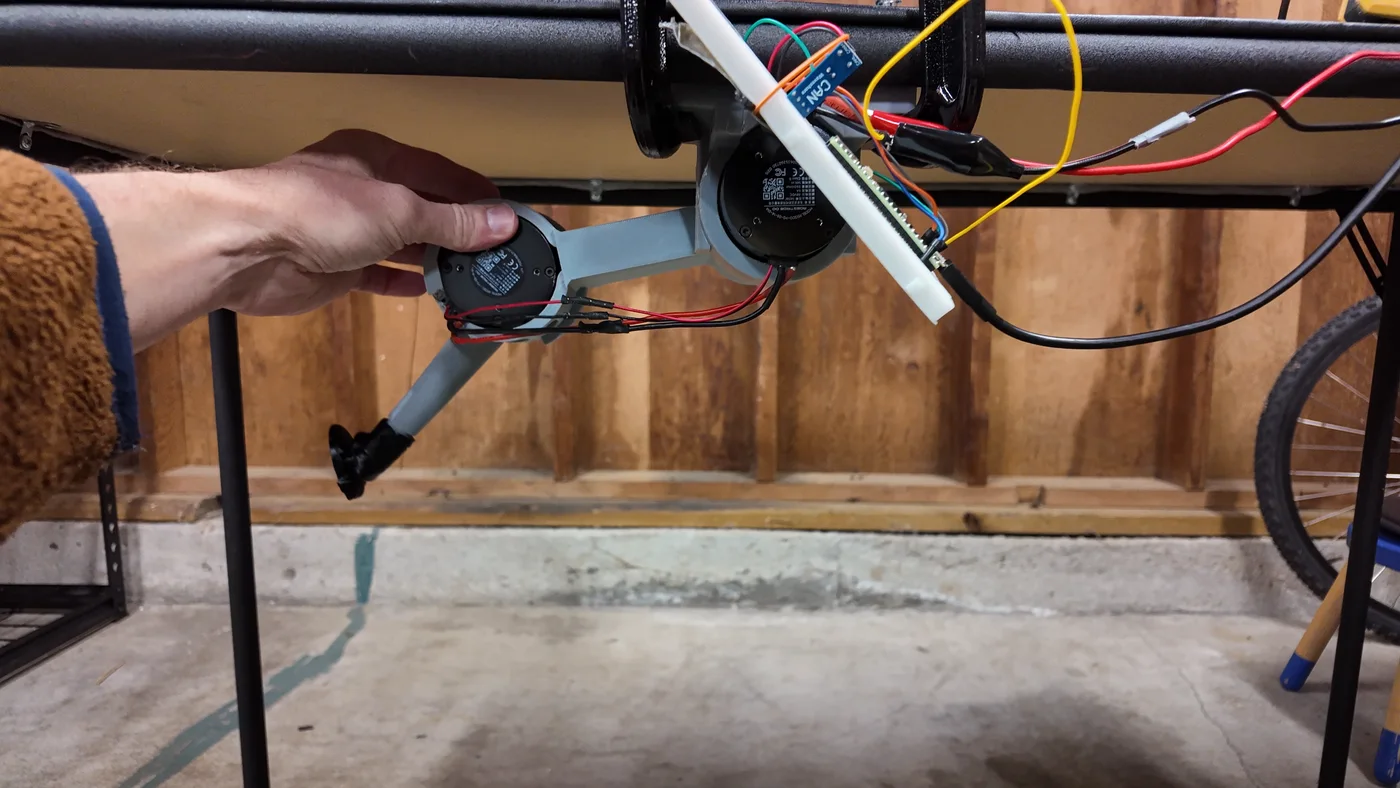
Watching that video closely, though, the leg did swing past hanging once when I let it go from high up, then settled. One swing isn't enough to time a period, but there's another way. I simulated the fall with different values for inertia and friction and kept the one that matched the logged angle best. The match was very good, within 0.04° on average. Other inertia values didn't fit nearly as well.
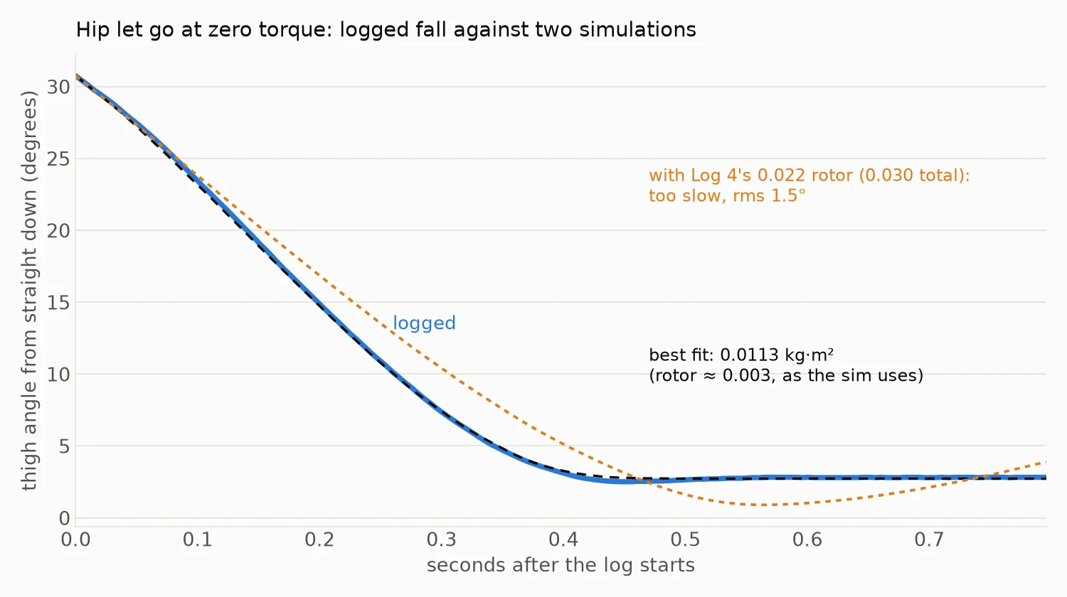
The best fit puts the inertia at 0.0113 kg·m² about the hip. The leg's own share, from the CAD model, is about 0.0086, which leaves about 0.003 for the motor's spinning parts. That's the value the simulation has used all along. Friction came out at about 0.15 N·m, also close to what the simulation assumes.
This changes one conclusion from Log 4. There I wrote that the inertia from an earlier bench test stood, at about 0.022 kg·m². This test rules that out for the hip motor. My best guess is that the earlier test also counted the lever bolted to the motor, but I haven't checked that yet. Either way, the simulation runs I redid with 0.022 should go back to 0.003.
Next steps
The firmware for the last two checks is written and on the Teensy. The endurance run will loop the walking gait for 30 to 40 minutes, then I'll check every bolt and the knee and hip bosses for loosening, cracks or wear. The foot press puts a bathroom scale under the foot at the standing pose and pushes down in steps up to about 2 kg. The scale reading should match the force the motor torques predict. After that, one thigh in PAHT-CF and a small test piece for the heat-set inserts, before printing the full set.
Log 9: Kicks, and a hidden torque limit (November 1, 2026)
The morning started with check 6, the foot press. The first run worked mechanically, but the bathroom scale read 1.5 to 2 times the force the motor torques predicted, so that check isn't passed yet.
Then something more fun: a kick test. A kick pushes the motors much harder than the slow walking gait, so it tests speed and torque. The first version was a small scoop under the hip, which looked nothing like a kick. The second swung the leg from far back to far forward. The version that stuck is a whip kick: the leg starts almost straight and far back, the hip swings forward, and the knee snaps the foot through at the end, the way a person kicks a ball.
I ran it as a ladder, speeding up one step at a time. Each speed is how fast the foot is moving at its fastest point.
| Foot speed | Whole kick | Peak hip speed | Peak knee speed |
|---|---|---|---|
| 1 m/s | 1.2 s | 2.9 rad/s | 3.0 rad/s |
| 2 m/s | 0.6 s | 5.7 rad/s | 6.1 rad/s |
| 3 m/s | 0.4 s | 8.6 rad/s | 9.5 rad/s |
| 4 m/s | 0.3 s | 12.3 rad/s | 13.3 rad/s |
Getting to 4 m/s took some work. The first try at that speed stopped itself halfway, because the knee fell too far behind its planned path and the safety check cut it off. Two changes fixed it: stiffer control during the swing only, and spreading the knee snap over a longer part of the kick so the knee needs less torque.
Kicking things
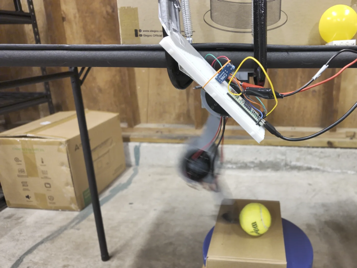
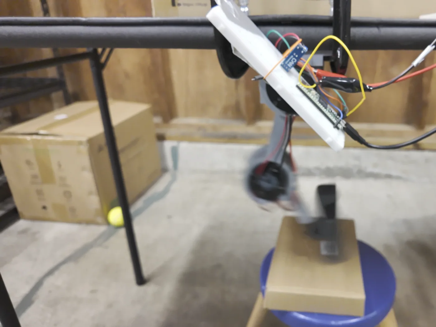
Next came five more 4 m/s kicks, five seconds apart, with something new on a box each time: a tennis ball, a ball held in my hand, a toy car, a black object, and finally nothing. The motors log their torque 500 times a second, so every hit shows up as a spike. From the extra torque at the moment of contact, and the leg's geometry, I can estimate how hard the foot hit.
| Object | Result | Foot force (estimate) |
|---|---|---|
| Tennis ball | Knocked off the box | about 36 N |
| Ball in my hand | Glancing hit | about 20 N |
| Toy car | The foot swept just over it | none |
| Black object | Knocked off, and the foot pad broke | about 54 N |
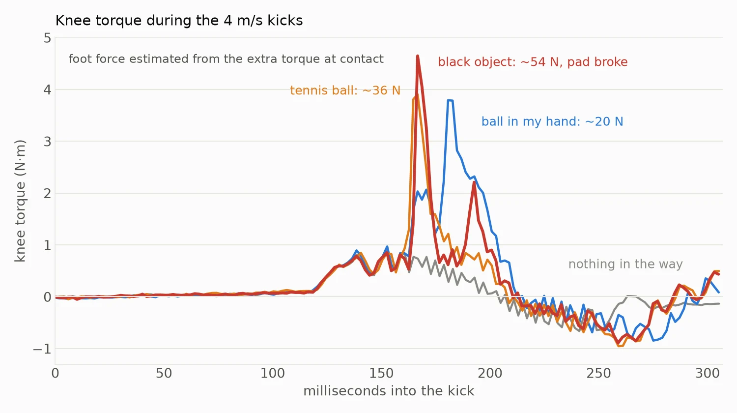
The hardest hit broke off the PLA foot pad. Before the test I had guessed the printed foot would handle about 35 N from the side. The 36 N tennis ball was fine and the 54 N hit wasn't, so that guess was about right. The next foot needs to handle at least 60 N with some margin.
A hidden torque limit
Something had bothered me all day. In fast moves the knee never seemed to make much more than 1 N·m, even when the controller asked for much more. Yet during the hits it showed 4.7 N·m. So I gave each motor short torque pulses with the leg swinging freely, and worked out the torque it really delivered from how fast the leg sped up. Both motors fell far short: asked for 4 N·m, the knee delivered about 0.9 in a 10 ms pulse and the hip about 2 in 20 ms. Held still and given time, they always got there. The motors just couldn't build torque quickly.
I ruled things out one at a time. The 48 V supply didn't sag at all during the pulses. A filter setting that looked suspicious in the manual made no difference. What did matter was the gain of the motor's current loop, the controller inside the motor that pushes current through the windings. The factory value is 0.125. Raising it to 0.5 made the current rise about four times faster.
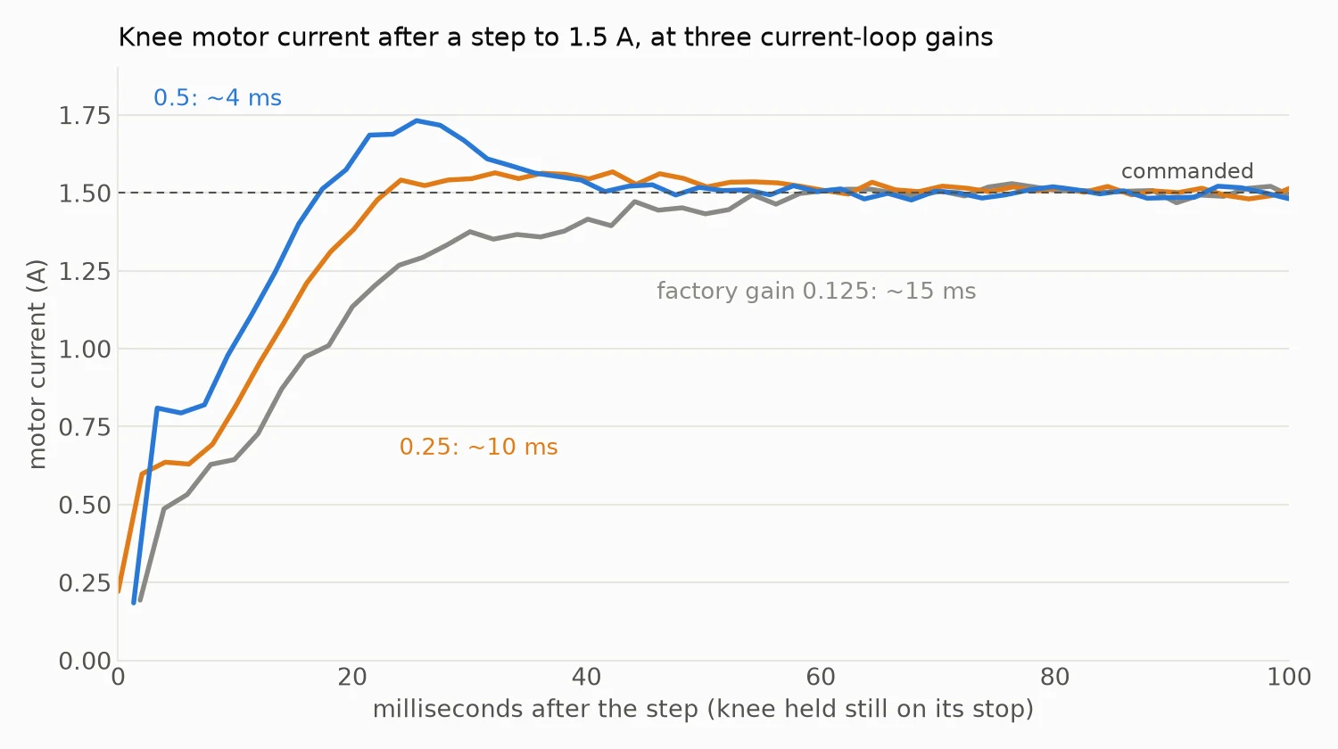
| Measurement | Factory gain (0.125) | Gain 0.5 |
|---|---|---|
| Current rise time (time constant) | 11 to 15 ms | 3 to 5 ms |
| Knee torque from a 4 N·m, 10 ms pulse | about 0.9 N·m | about 2.1 N·m |
| Hip torque from a 4 N·m, 20 ms pulse | about 1.8 N·m | about the full 4 N·m |
| Knee off its path in the 4 m/s kick | 3.6° | 1.2° |
This is a big deal for the robot. Catching a stumble, landing a jump or swinging a leg fast all need torque within a few milliseconds, and the simulation assumes the motors can deliver it. With the factory setting they couldn't. For now the new gain isn't saved in the motors: the Teensy sets it before each fast test, and a power cycle restores the factory value. I've asked RobStride whether 0.5 is safe to keep.
One more lesson from the day: flashing the Teensy kept hanging for an hour. The cause turned out to be Google Chrome holding the board's USB connection open. Closing Chrome before flashing fixed it.
Next steps
A stronger foot, made to take at least 60 N. The sharper, later knee snap I wanted for the kick, which should work now that the knee can build torque quickly. A longer run of fast kicks to check heat with the new gain. And the foot press, to sort out why the scale and the motor torques disagree.
Log 10: Hopping under a heavy beam (November 2, 2026)
Until now the leg had only moved its own weight, swinging in the air. A real leg has to hold up part of a robot, push it and catch it again. So this time I gave it something heavy to carry.
The setup is simple. A wooden beam lies flat on the table with one end sticking out over the edge. The hip mount is C-clamped under that end, and the foot stands on a rubber mat below. A brick sits on the far end of the beam. When the leg straightens, it lifts its end of the beam off the table. The leg measures the load itself from the knee torque, and it came to about 11 to 18 N, the weight of 1.1 to 1.8 kg on the foot. Later I took the brick off and held the far end by hand, which made it 21 to 25 N.
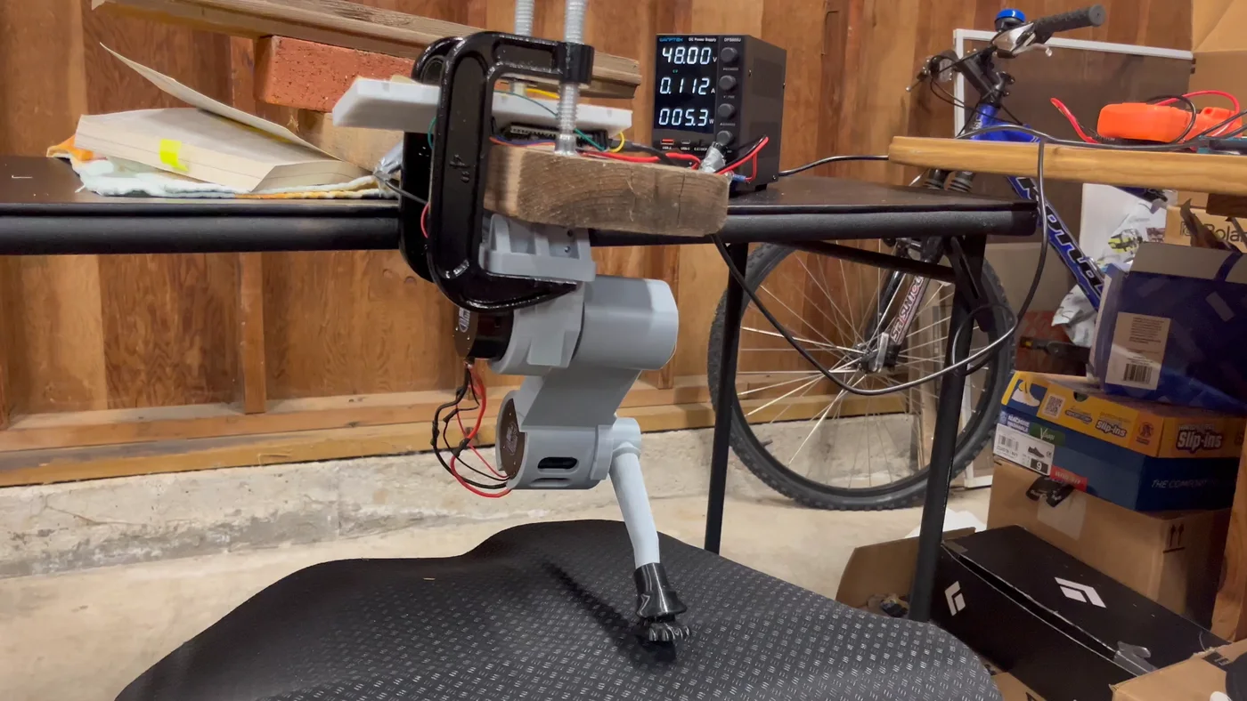
Holding and bouncing
First, two 30-second holds: 11 N with the foot 224 mm below the hip, and 22 N at 245 mm, where the beam end rose 7.5 cm. Both were steady. Then four bounces, with the foot moving up and down in a smooth wave, from 10 mm once a second up to 20 mm twice a second. The knee never needed more than 2.3 N·m, and the motors stayed at 25 to 27 °C.
Single hops
A hop here means the leg pushes down fast enough that the foot leaves the mat, then catches the beam as it comes back down. I asked for faster and faster pushes, measured as the speed of the foot at the end of the push.
| Push asked for | What happened | Peak knee torque |
|---|---|---|
| 0.3 m/s | The foot barely left the mat | 2.1 N·m |
| 0.5 m/s | About 0.1 s in the air | 3.0 N·m |
| 0.7 m/s | First try stopped itself (see below), then 0.65 m/s | 4.5 N·m |
| 1.0 m/s | Launched at only 0.73 m/s | 5.9 N·m |
The first 0.7 m/s try was stopped by a safety check, because the top of the push came too close to a fully straight knee. Lowering the top of the push fixed that. For these hops I also used the higher current-loop gain from Log 9, and it made a clear difference. With the factory value the knee trailed its command by 10 to 14 ms during a push. With the new value that dropped to 2 to 4 ms.
The 1.0 m/s hop fell short, but the motor wasn't the reason. The knee reached 5.9 N·m with 8 allowed. The push only lasts about 54 ms, and my controller doesn't yet ask for enough torque early enough. That's a software fix.
Successive hops
Chaining hops is harder. Each landing has to be detected, slowed down and turned straight into the next push. Catching the beam with plain soft control let the knee sag up to 0.3 rad. So instead the leg follows a planned slowdown path as it lands, and the motor stiffness ramps back up during it. That kept the knee within about 0.1 rad of its path. Ten hops in a row at 0.7 m/s ran cleanly.
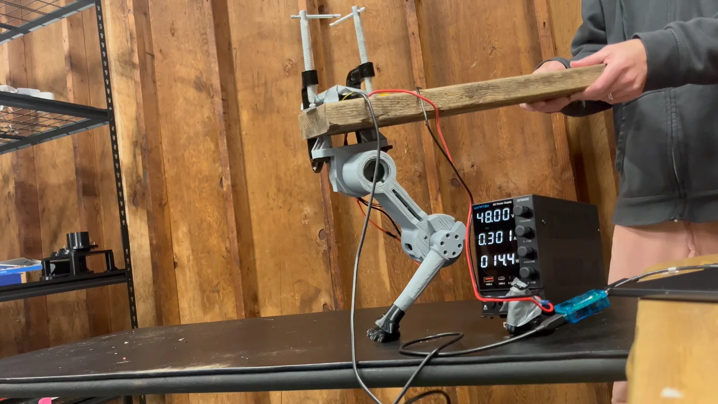
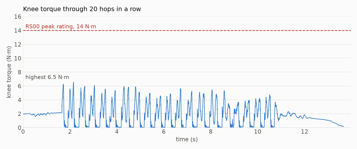
At 0.8 m/s two new problems showed up. First, the beam pumps up. Each push lands while the beam is still moving, so with the same push every time the hops got higher and higher, from about 0.1 s in the air to as much as 0.25 s. The fix was to adjust each push based on how long the last hop stayed in the air. Second, the foot kept pushing about 50 ms longer than planned, because of the remaining lag. So the leg now times each hop from the moment the knee actually unloads. With both changes, 20 hops in a row at 0.8 m/s worked, twice. The second run aimed for 0.163 s in the air and averaged almost exactly that.
What the motors showed
- Torque was never the limit. The hardest knee push was 6.5 N·m, about 46% of the RS00's 14 N·m peak rating.
- Speed and power have room to spare. The knee peaked at about 10.7 rad/s, around 40% of its rated speed, and about 65 W of its rated 140 W.
- Heat didn't matter in these short tests. Every run stayed at or under 26 °C, and 20 hops warmed the knee by only 3 to 5 °C. The big heat question is still long walks, which this doesn't answer.
- The hip worked harder than I expected on landings, up to 5.7 N·m. The foot often landed a bit off-center, and the hip dragged it back. Next time the leg should plan from where the foot actually lands.
The weak link: a power wire
The knee motor's 48 V wire pulled out of its plug twice during chained hops. I soldered it back on. The lesson is that the leg cables need strain relief before this leg walks or hops on a robot.
A spark from the capacitors
Later, when I moved the power supply, the capacitors fell out. When I put them back in, with the supply off, there was a spark. When I checked them with a multimeter, they showed over 3 V, even though they were unplugged from the supply. I discharged them through a resistor for a few seconds until they read under 1 V, and the next try had no spark. Both motors were fine afterwards. The lesson here is to tape the capacitors tightly to the power supply, and to check their orientation when putting them back in.
Next steps
Strain relief for the knee cable. A better push that actually reaches 0.9 to 1.0 m/s. Planning each hop from where the foot lands. Then a slow squat under the beam, stepping in place under load, and finally a long run to test knee heat.
Log 11: First powered tests of leg 2.0b (November 4, 2026)
Today the new 2.0b leg went onto the beam rig. I wanted to know three things. Does it drive correctly, does it heat up differently from the old leg, and can it hop?
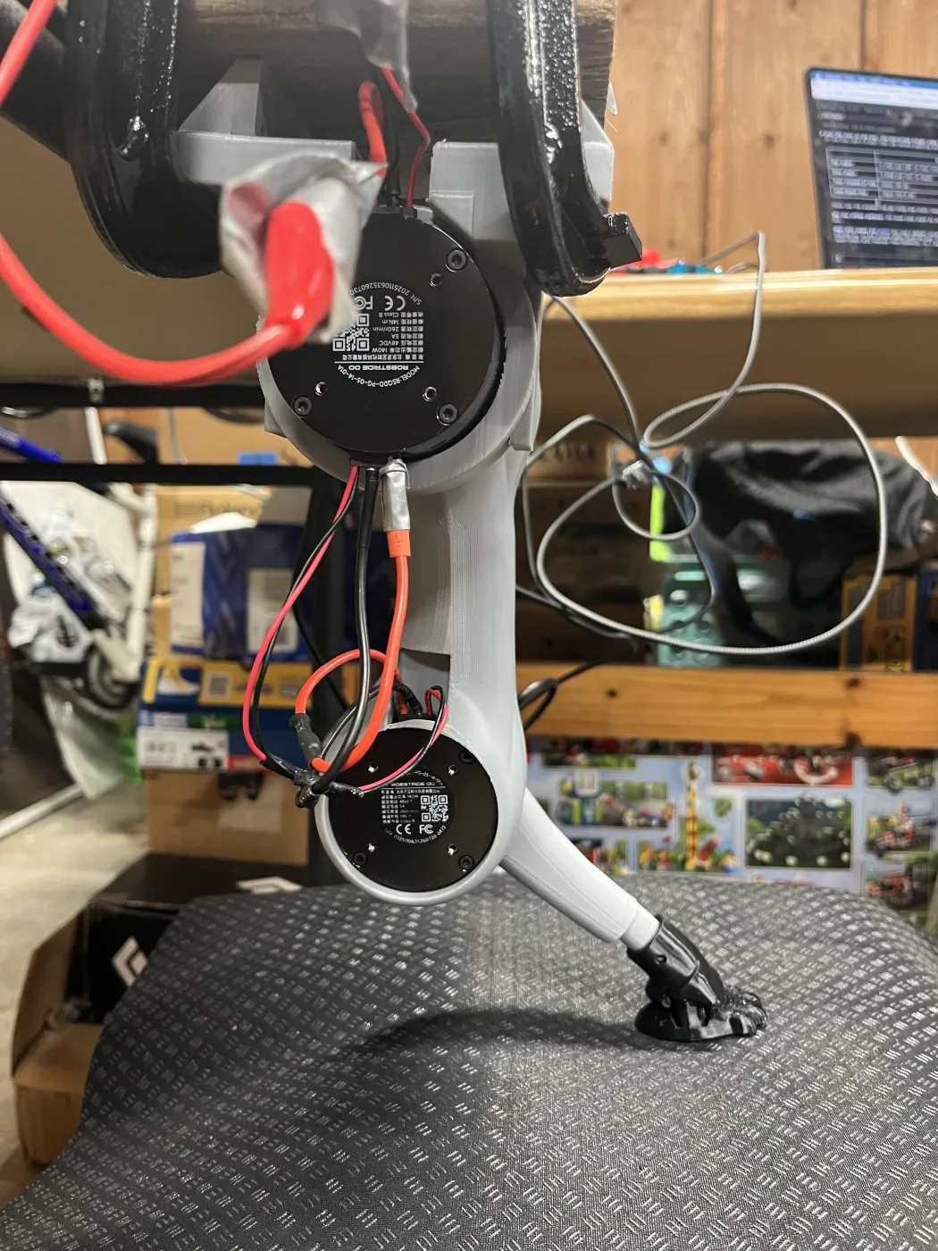
First power-up
Both motors answered right away with no faults. The new mount changed the hip's zero by about 2.1 rad, so the old limits were useless. With the motors off, I held the thigh plumb and moved each joint by hand while the angles were recorded. The first powered run kept the foot in the air, and tracking stayed within 0.007 rad.
Heat runs
Next I repeated the 1.5 Hz bounce from my last test of the old leg, the 1.0f version. The table skips the first two minutes of each 10-minute run, except for the long run, which skips the first 20 seconds of each run.
| Run | Average load | Average knee torque | Knee motor temperature |
|---|---|---|---|
| Old leg, 10 minutes | 21.7 N | 1.49 N·m | 20 to 30 °C |
| 2.0b leg, 10 minutes | 17.3 N | 1.19 N·m | 24 to 30 °C |
| 2.0b leg, 30 minutes | About 18 N | About 1.25 N·m | 38 to 48 °C |
The 2.0b leg's knee rose more slowly, but it was also carrying less. Motor heating grows with the square of the torque, and that alone predicts almost the whole difference. So I can't say the new leg runs cooler. It does look about the same, which is still good news.
After 30 minutes the knee was at 48 °C and still rising, at about 0.2 K/min. I still haven't found where it levels off. This load is also under half of what a leg should carry in a trot, so the knee heat question stays open. After an earlier run, with the knee motor at 40 °C, the thigh beside it felt only a tiny bit warm.
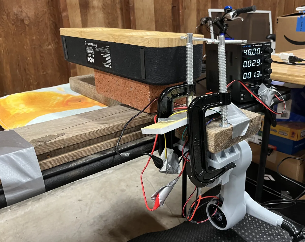
Two small things changed the numbers a lot. The brick and speaker in the photo doubled the knee torque during a slow squat. Then, during one long run, a book under the mat slipped and the load sagged to about 13 N until I put it back. For a test like this, the foot needs something solid to stand on.
Hopping
For the hops I held the beam in my hands, as I did with the old leg. The first run taught me something right away. Every run ends with the foot rising and both motors switching off. With nothing else holding the beam, it nearly crashed down, and I had to catch it. Now the computer says "take the weight" out loud a few seconds before that happens.
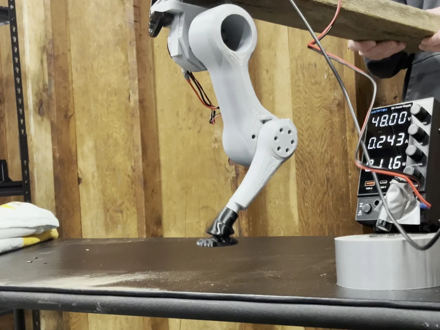
| Push asked for | What happened | Peak knee torque |
|---|---|---|
| 0.5 m/s, one hop | Finished normally | 3.4 N·m |
| 0.7 m/s, one hop | Finished normally | 4.3 N·m |
| 0.7 m/s, 10 hops | All 10 landed, 0.12 to 0.2 s in the air | 5.6 N·m |
| 0.8 m/s, 10 hops | All 10 landed, 0.13 to 0.19 s in the air | 5.5 N·m |
| 1.0 m/s, 10 hops | Both motors faulted on the first hop | 6.3 N·m before the fault |
Up to 0.8 m/s the 2.0b leg hopped about as well as the old one, and nothing cracked or came loose. The motors stayed near 42 °C through the sets, even though they started warm.
The 1.0 m/s fault
At 1.0 m/s, both motors reported overcurrent at the same moment, right at the end of the push. They shut off, and the leg went limp. Afterward both answered normally, with no faults left.
My best guess is the bench supply. I think its current limit, the most current it will deliver before it holds back, was set to 1 A. At 48 V that allows only 48 W for both motors. Just before the fault, the knee alone was putting out about 70 W of mechanical power. I'm not sure yet, because the motors reported overcurrent instead of low voltage, and I wasn't logging the voltage during the hop.
Next steps
- Raise the supply's current limit to 4 A, check the motor wires, then try the same 1.0 m/s push as a single hop.
- Run a heat test near the torque the simulation predicts for walking at 1 m/s, about 2.6 to 3.0 N·m, starting from cold.
- Give the foot a solid surface so the load stays steady.
Log 12: Printing a palm-sized figure (November 4, 2026)
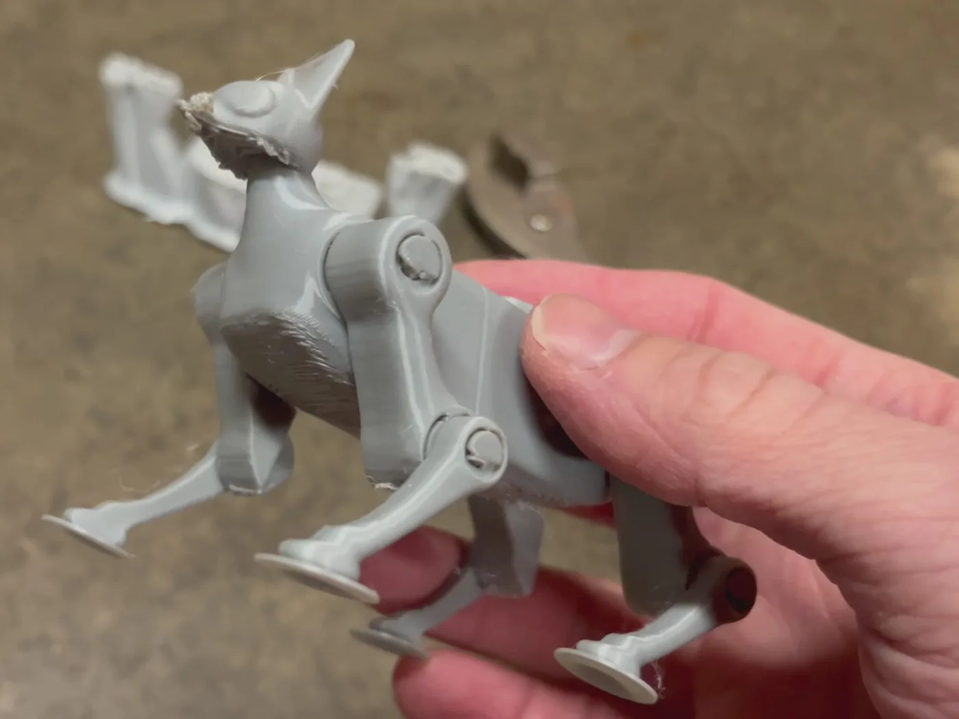
Between leg tests, I wanted a small model of the 2.0 design that I could hold in my hand. It's 1/6 scale, about 113 × 60 × 70 mm, and uses about 48 g of gray PLA. I expected an easy side project. It took four full prints.
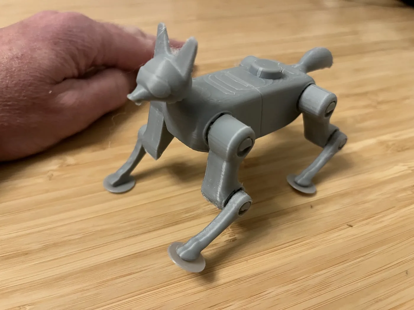
Joints that print assembled
My first plan was hinges made from pieces of 1.75 mm filament. Cutting and fitting that many tiny pins by hand didn't appeal to me, so I cancelled the test part as it started. The figure became print-in-place, which means it comes off the printer in one piece with its joints already together. Each joint has a small toothed wheel and two spring arms, so a leg clicks from one position to the next and holds there.
Small test joints came first. Hip settings were easy to choose, but one knee wouldn't move at all and another hurt my fingers. Those test levers reached only about 7 mm, while the real shank reaches 20.7 mm, so I printed a second set of knees with full-length levers. The best one was still a little too light, so the figure uses a slightly stiffer setting that I never tested on its own.
Four prints
| What changed | What happened | |
|---|---|---|
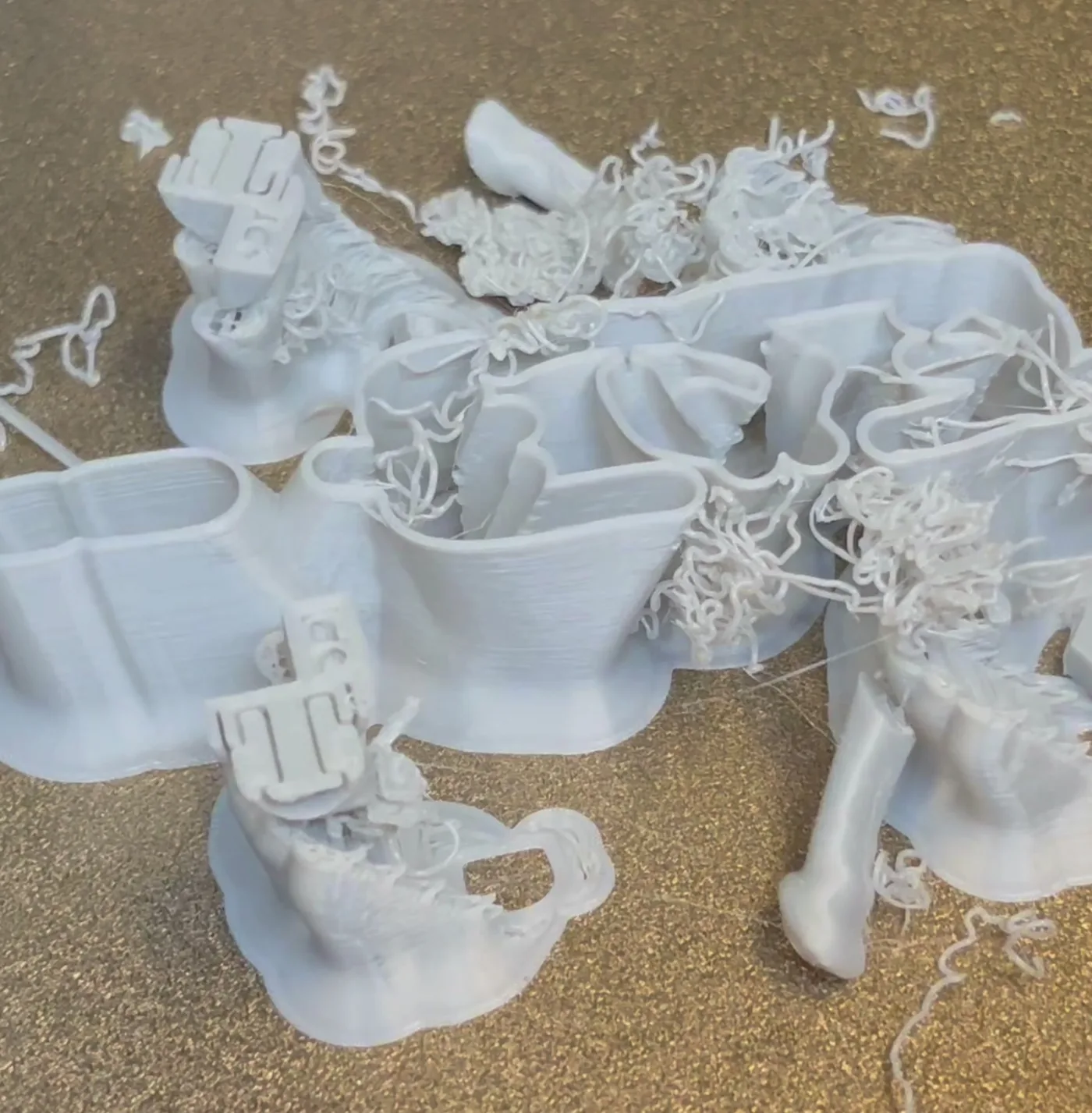
| 1 | Fast settings, slim tree supports | Body fine, all four legs spaghetti, stopped at about 4 hours |
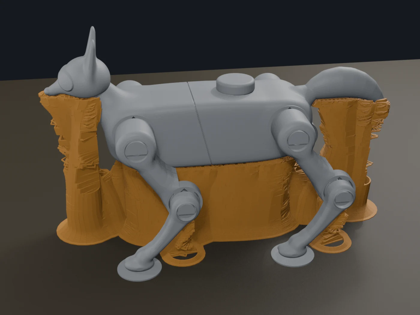
| 2 | Much slower, stronger supports, nozzle lifts on every long move | Lower legs clean, pieces came loose at about 18 mm, stopped at about 3 hours |
| 3 | Medium speed, tiny break-away tabs across the joints | Pieces came loose at about 18 mm again, stopped at 100 minutes |
| One leg | A flat pad under the paw, bed held at 65 °C | Passed the trouble height, 44 minutes and about 4 g |
| 4 | Pads on all four paws, bed held at 65 °C | Finished in 6.5 hours, legs move and click |
Two wrong guesses
After print 1, I blamed speed and supports. Those changes did clean up the lower legs, so they may have helped, but the print still failed. Watching print 2's timelapse from the printer's camera, it looked as if a thigh had lifted off its support. That made sense, because each thigh starts as a loose island on top of a support, with nothing else holding it. So I added break-away tabs to tie the parts together.
Print 3 failed at the same height, even with the tabs and at a very different speed. That ruled out speed as the deciding factor. Then I took a close-up video from above, which I should have done much earlier. It showed clean, empty holes in the supports where the paws had been, and a whole shank lying flat on the plate. The paws were peeling off the bed.
Each paw touched the bed with only about 14 mm², and it had a tall, leaning leg above it. A normal slicer brim, a thin ring printed around a part to help it stick, wouldn't work well here because the supports crowd it out. So I added a 14 mm round pad to the model under each paw. Contact area went from about 55 mm² to 615 mm² in total. I still don't know exactly why the peeling starts at about 18 mm. My guess is that the plastic pulls harder as it shrinks once the thighs get wider.
Testing one leg first
This time I didn't jump straight to another full print. One leg printed past the failure height took 44 minutes. That test wasn't proof, since a single leg cools differently from a full plate, but it passed. The failed prints had already used about 8 hours.
Print 4 got through the trouble height cleanly. At about 44 mm, a small piece broke loose near the tip of the tail, which also starts as a loose island. It stayed a single piece and the rest was fine, so I let the print run. The hips and knees all click. The pads are hard to peel off, so they stay on as little feet.
Lessons
- Test the riskiest part first, and print it past the height where trouble is expected.
- Take a close-up photo or video before deciding what went wrong.
- Compare where each failure happens. Two prints failing at the same height at very different speeds said a lot.
- Check how much area touches the bed, especially under tall, leaning parts.
The slicing script now warns about small bed contact automatically, so the next print of this kind should catch the problem sooner.
Log 13: Hand-held hops up to 1.1 m/s (November 6, 2026)
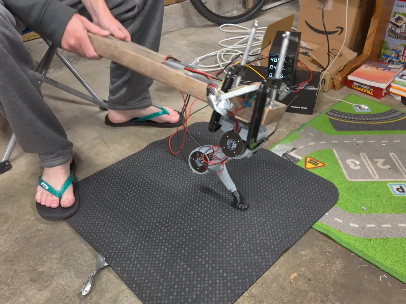
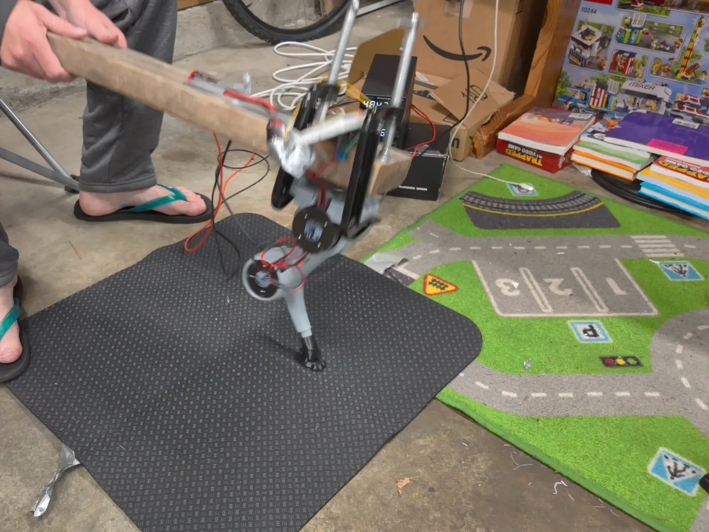
Two days ago, the 1.0 m/s hop in Log 11 ended with both motors faulting on the first push. My best guess was the power supply, which I remembered being limited to about 1 A. Tonight I raised the limit to 4 A and went back to find out. The leg ended up doing 10 hops in a row at 1.1 m/s, faster than I had planned to go.
A swap after the rebuild
I had just rewired and rebuilt the leg, so I checked it by hand before any powered move. With the motors off, I moved each joint to its ends while the angles were read back. Folding the knee moved the motor called the hip, and moving the hip moved the motor called the knee. The two motors had traded places during the rebuild without my noticing.
Sending hip commands to the knee would have been a bad way to find out. Swapping the two saved CAN IDs fixed it with no disassembly. The joint ranges and zero positions were measured again, since the old numbers came from the other motor in each joint. A slow move in the air then landed within 0.004 rad of where the math predicted.
Trying to go hands-free
Holding the rig means my hands share the load, so I tried letting the beam rest on a box instead, with weight on its far end. The hip height took several tries to get right, and reading the angles with the paw on the mat worked much better than a tape measure. Hops at 0.5 m/s ran without a fault, but the beam rolled and crept sideways. The thigh also seemed to press against the box in some runs, which showed up clearly as hip torque while the foot was in the air. Weights and moving the rig didn't cure it. The beam needs a real pivot, so I went back to holding it for now.
Stepping up the speed
I held each step for 10 hops in a row and checked the numbers before the next one. The 0.5 m/s run used separate hops with a pause between them. The rest were continuous, with each landing running straight into the next push, about two to three hops per second.
| Push | Hops | Time in the air | Knee peak | Hip peak | Hottest motor |
|---|---|---|---|---|---|
| 0.5 m/s, separate | 10 of 10 | Not measured | 3.6 N·m | 3.8 N·m | 32 °C |
| 0.7 m/s | 10 of 10 | 110–158 ms | 6.9 N·m | 2.5 N·m | 33 °C |
| 0.8 m/s | 10 of 10 | 130–154 ms | 6.7 N·m | 3.1 N·m | 34 °C |
| 0.9 m/s | 10 of 10, twice | 158–199 ms | 6.8 N·m | 4.1 N·m | 36 °C |
| 1.0 m/s | 10 of 10 | 169–195 ms | 7.2 N·m | 3.7 N·m | 37 °C |
| 1.1 m/s | 10 of 10 | 188–215 ms | 7.4 N·m | 5.0 N·m | 33 °C |
The 1.0 m/s run is the one that faulted on November 4. This time, it ran with no faults. That supports the supply limit as the cause, but it isn't proof, because the leg had also been rebuilt.
Getting past 1.0 m/s
The firmware refused anything above 1.0 m/s, so I raised that cap. Then it refused the 1.1 m/s plan too, because the top of the hop would have brought the knee too close to straight. Starting the whole push 5 mm lower fixed that, with the same 27 mm of travel.
The first try at 1.1 m/s stopped itself after two hops. The second hop stayed in the air longer, about 270 ms, and absorbing that landing would have taken the foot below the firmware's lowest allowed height. So it caught the leg and ended the series, as designed. I can't tell whether the leg really flew that long or my hands lifted it. On the next try, I held the rig steadier, and it did all 10.
What the motors showed
The knee holds about 7 N·m through most of a push, and its speed peaks at about 13 rad/s just as the torque starts to fall. Compared with 1.0 m/s, flights ran about 10% longer. Using the time in the air, that's about 5.2 cm of height against 4.4 cm.
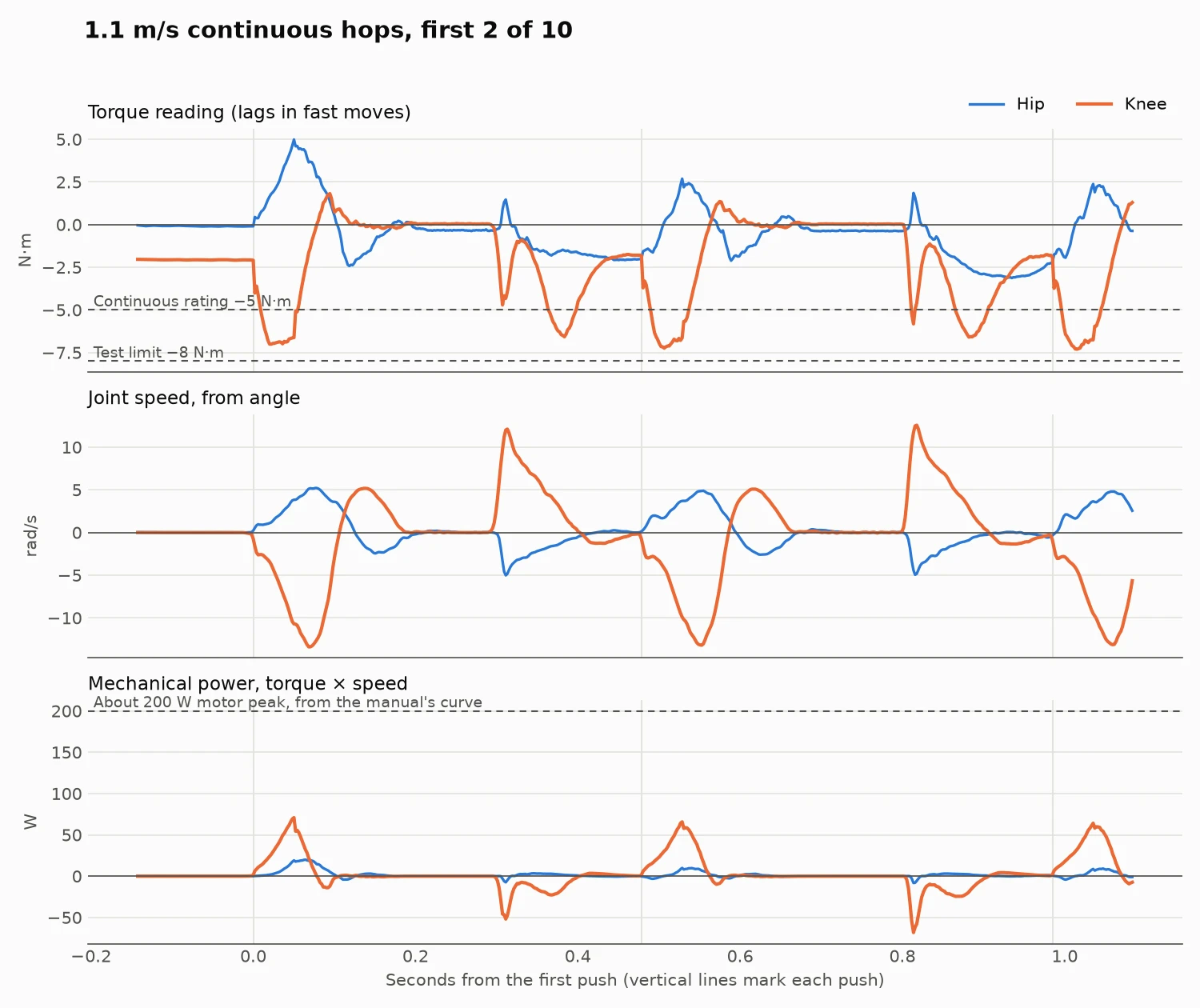
I didn't measure supply current during these runs, so the chart below is an estimate from the torque and speed, using the heat test's power readings for the losses. It suggests a peak of about 3.7 A at 1.1 m/s, close to the 4 A limit, for only about 50 ms.
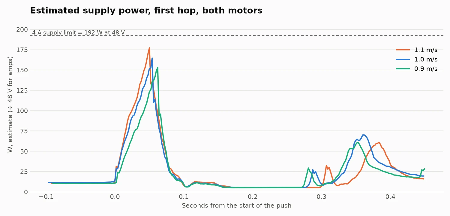
The RS00's manual publishes a torque-speed curve at 48 V. A spinning motor generates a voltage that fights the supply, so torque falls as speed rises. The curve shows 14 N·m at 100 rpm, about 9.5 N·m at 200 rpm and almost nothing at its 315 rpm top speed. Reading that chart, torque times speed peaks at about 200 W.
At 1.1 m/s, the knee's top speed was about 13.4 rad/s, or 128 rpm, where the curve allows about 13 N·m. The knee read 7.4 N·m. Its peak of about 71 W is roughly 35% of that 200 W, so the motors have room left. For this short push, my rough guess is that the motor alone could reach about 1.4 to 1.5 m/s. My 8 N·m test limit, the supply, the knee's distance from straight or the printed parts will probably stop it first.
Still open
- My hands are part of these numbers. The leg still has to show this with no one holding it.
- The beam rig needs a real pivot before it's useful for hops.
- Motors that switch off under load drop the leg, and this nearly caught me out again after one hop. I've written a gradual shutdown that fades torque under damping, but I haven't verified it yet. The real robot will need to sit down first, then ease off.
The printed leg looked fine when I checked it after the 1.0 m/s run.
Log 14: A long jump contest in simulation (November 7, 2026)
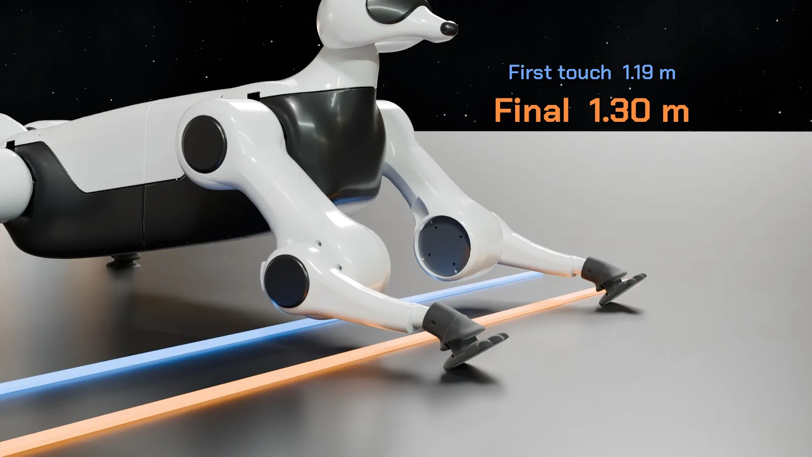
While the real leg waits for its next test, I wanted to see what the full 2.0c robot could do if I asked it to jump as far as possible. So I set up an Olympic-style long jump in MuJoCo: run up, jump at a line, and measure where the paws end up. Over two days, training tried five different jumping styles. The winner reached 1.30 m, and the losers taught me just as much.
The rules
- Every attempt starts from a standstill 4 m before the line.
- The nearer front paw is measured. A blue mark shows the first touch, and an orange mark shows where the paws stop after sliding. The orange one counts.
- Stepping past the line before taking off is a foul.
- Only the feet may touch the floor during the jump. A knee, thigh or shank on the floor voids the attempt.
- One landing only, and the front feet have to land first.
- No flips.
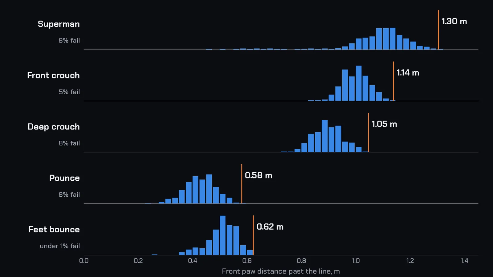
Each style got 400 attempts, and its best legal jump is the one shown. Small random differences in each attempt, like sensor noise, make every run a little different.
How the jumps were trained
My first plan was reinforcement learning, the same method that taught the robot to walk. Nine trial runs all failed to produce a jump. The robot forgot how to run, stalled, or slammed its joints as soon as training began.
So I split the job in two. The walking controller I already had does the run-up. At a chosen moment in its stride, a scripted jump takes over: crouch, push, flight and landing, each a pose for the front and rear legs, with left and right mirrored. That's 23 numbers in all, covering the pose angles, how long each phase lasts, and when the jump starts.
An evolutionary search called CMA-ES tunes those numbers. Each generation tries 64 sets of numbers, every set from 32 slightly different starts, so 2,048 simulated jumps. The best ones steer the next generation. On the Predator's GPU, a generation takes about 12 seconds, and a full run of 100 to 150 generations takes about half an hour. In the video, each generation is called a training cycle.
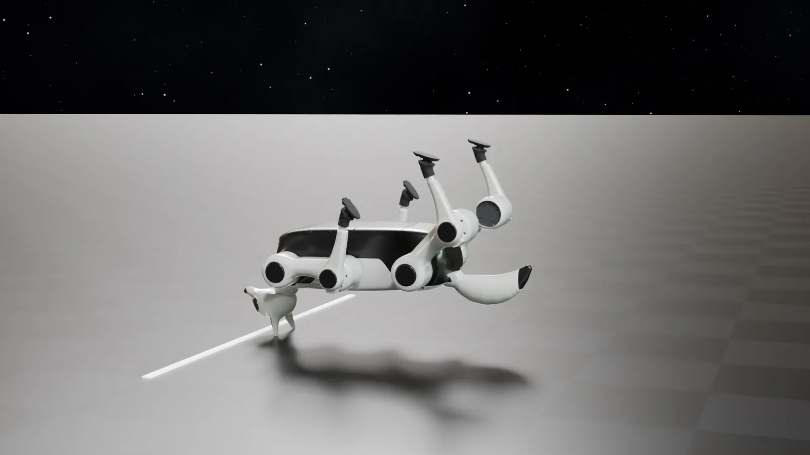
One run shows how quickly it improves. At cycle 0, none of 24 test jumps was legal. By cycle 5, a few were, at about 0.13 m. Cycle 60 reached 0.63 m, and cycle 145 reached 0.98 m, with 23 of 24 jumps legal.
Every rule found a loophole
Most of the rules above weren't in my first version. The search kept finding ways to score that a real long jump wouldn't allow, and each one became a new rule:
- It hopped a little, dropped onto its thighs and shanks, and bounced off them. That's where the feet-only rule came from.
- It flipped onto its front paws and hopped along upside down, landing more than once. Hence one landing only.
- It did a full somersault and landed on its hip motors. Hence no flips.
- It reached far with its front paws while the rear paws dragged in first. Hence front feet first.
An early version that measured the final mark differently let one run reach 1.86 m by bouncing. None of those results count.
Five styles
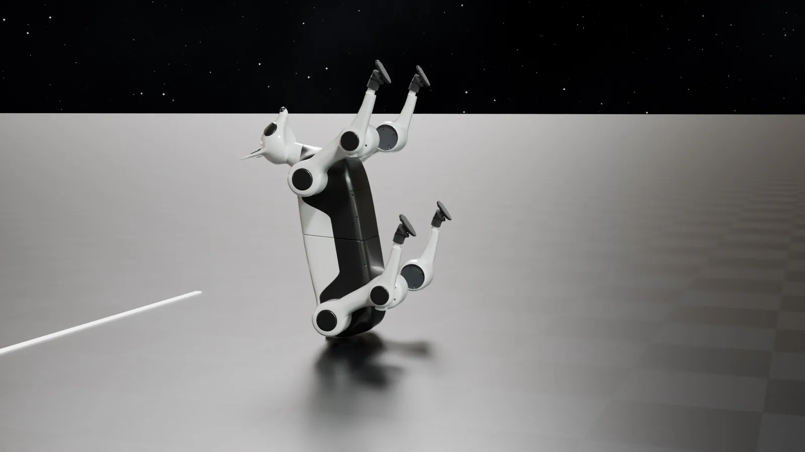
Left alone, the search always skipped the crouch. I suggested crouching first to load the legs, so some runs were forced to use a front crouch, a deep crouch or a pounce, while others stayed free. Here's how each did over 400 attempts:
| Style | How it jumps | Best | Average | Legal |
|---|---|---|---|---|
| Superman | Keeps its speed and stretches out | 1.30 m | 1.09 m | 92% |
| Front crouch | Dips its front, then springs | 1.14 m | 1.00 m | 95% |
| Deep crouch | Crouches low, then leaps | 1.05 m | 0.90 m | 92% |
| Feet bounce | A hop off the paws, no crouch | 0.62 m | 0.51 m | over 99% |
| Pounce | Slows at the line, then leaps high | 0.58 m | 0.43 m | 92% |
A sixth style, crouching with all four legs, reached 1.02 m. It looked too much like the front crouch, so it stayed out of the video.
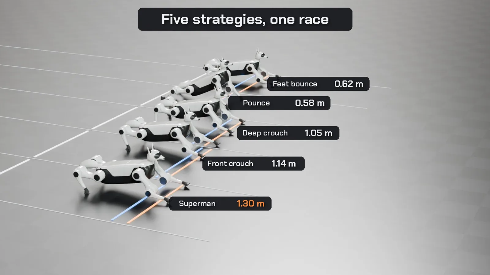
Why Superman won
Superman never crouches. It reaches the line at about 2.2 m/s, keeps that speed into the jump, and stretches its front legs far forward. The crouching styles store energy in their legs, but they lose speed doing it, and speed at the line turned out to matter more. I was surprised, since the crouch seemed like the obvious answer. For a while, the crouch was ahead, until more training and fairer tests changed the order.
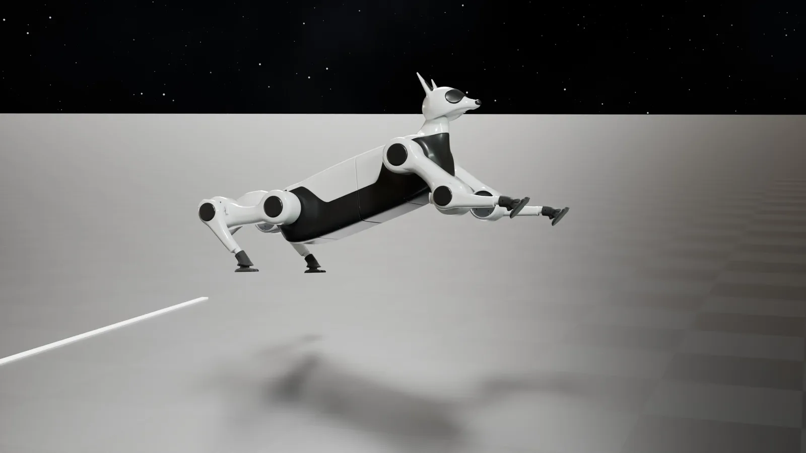
I also tried letting the legs move in mid-air to reach for the line. Starting from the same point, the average stayed at 1.09 m with or without the extra pose. That makes sense, since moving the legs in the air can't add speed, only shift where the paws end up.
Superman isn't the most reliable, though. Its worst legal jump was only 0.47 m, while the front crouch never landed short of 0.83 m.
Would it break?
Breakage didn't count in the contest, but I checked it afterwards. The loads from the best jumps went through the same stress check as the walking test, with the printed parts modeled as printed. On Superman's 1.30 m landing, the hip bends more than twice as hard as in walking, 55 against 23 N·m, and the foot force is 461 against 197 N. The weakest part checked was the shank, with a safety factor of 1.8. The thigh came out at 2.6 and the front body at 3.8.
That isn't a full answer. The lid, rear body, head and tail weren't checked, and neither was fatigue from jumping again and again. The lid was the weak point in the walking check, so it's the first thing to test if the real robot is going to jump.
Limits
- All of this is simulation, with no air drag, a flat floor and one robot design.
- The jump controller knows its exact distance to the line. The real robot would need a camera or range sensor for that.
- The simulation gives the tail no contact shape, so in some outtakes it dipped into the floor. The videos bend the tail clear in those frames. The physics is unchanged.
Making the videos
The jumps were recorded at 1,000 steps per second and rendered in Blender. That's about 4,000 frames across the two videos, split between the Predator, a Mac Mini and my MacBook, which took most of a day.
Log 15: The first printed body (November 8, 2026)
The rear half of the body finished printing early this morning. Like the front half two nights ago, it took about 12 hours and half a kilogram of PLA. Today I bolted the two halves together, screwed the flat floor plate on, and set the test leg and the breadboard with the Teensy inside. For the first time there is something on the bench that looks like a robot body.
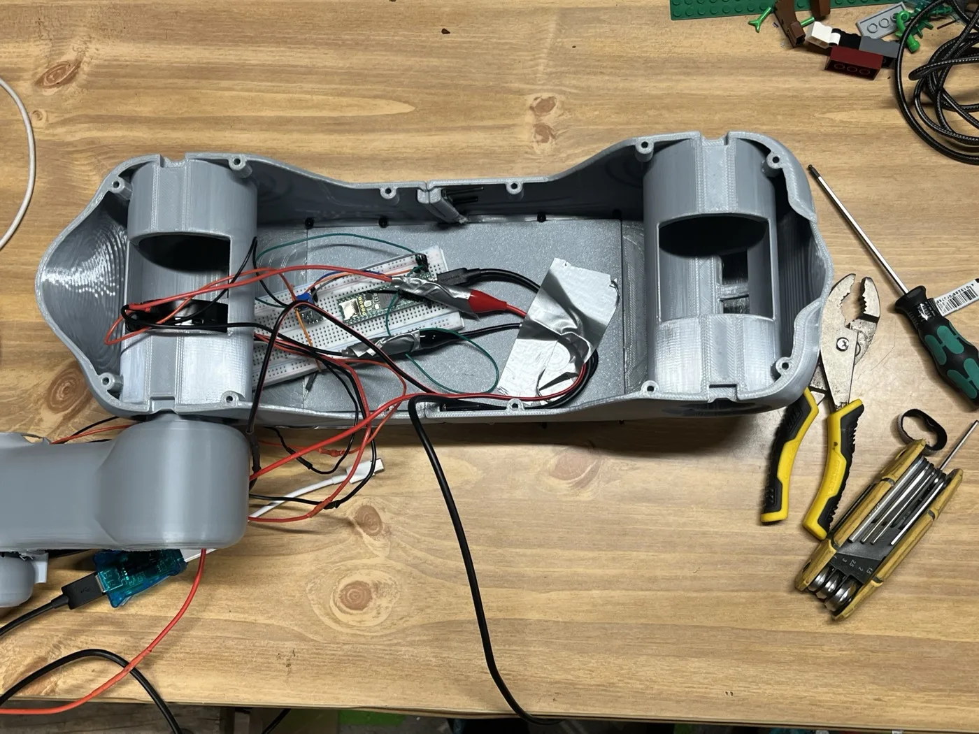
It went together, but not cleanly. The same problems I had with the front half showed up again on the rear, and a couple of them were worse.
Screw holes
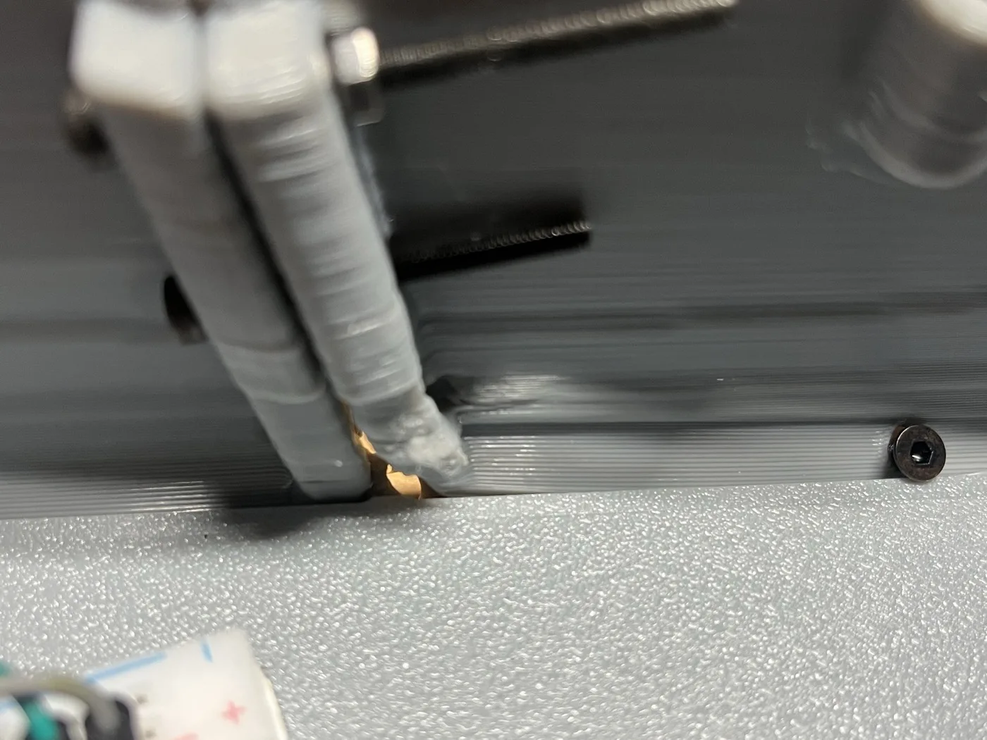
Some of the holes for the floor plate were not fully open where they come out of the tub, so the screws had to be forced through. The front half had this too, but the rear half was worse. Those holes sit where the floor curves up into the side wall, so the heads inside and the nuts outside both rest on a slope instead of a flat face.
The worst spots are the bolts that join the two halves. Each side has a column of three, and on both sides the bottom one came out damaged. That hole lands right where the wall meets the floor, and the plastic around it printed as a tangle, so the bolt won't go through. One side is much worse than the other.
Warping at the seam
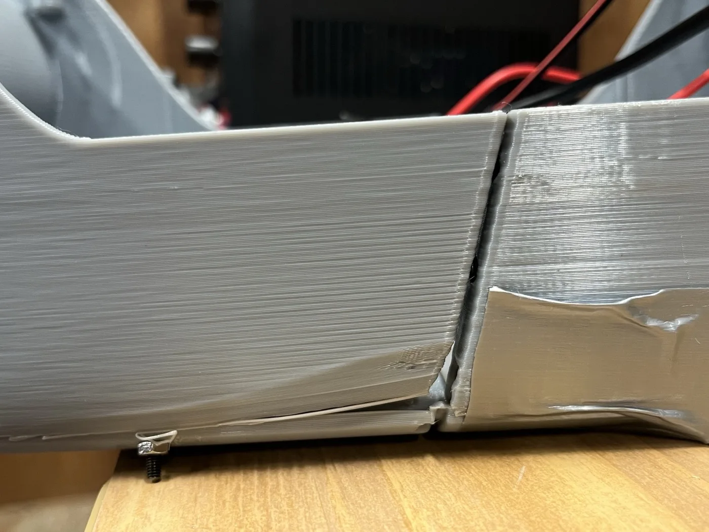
At the bottom of the seam, the lower edges of the two halves don't meet. One of them bows outward a little, which leaves a step and a gap. It's a long, thin edge with nothing holding it, so it moved either during the print or as it cooled. Tape along the bottom closes the gap for now, and it also backs up the floor plate, which only has a handful of screws holding it.
Supports
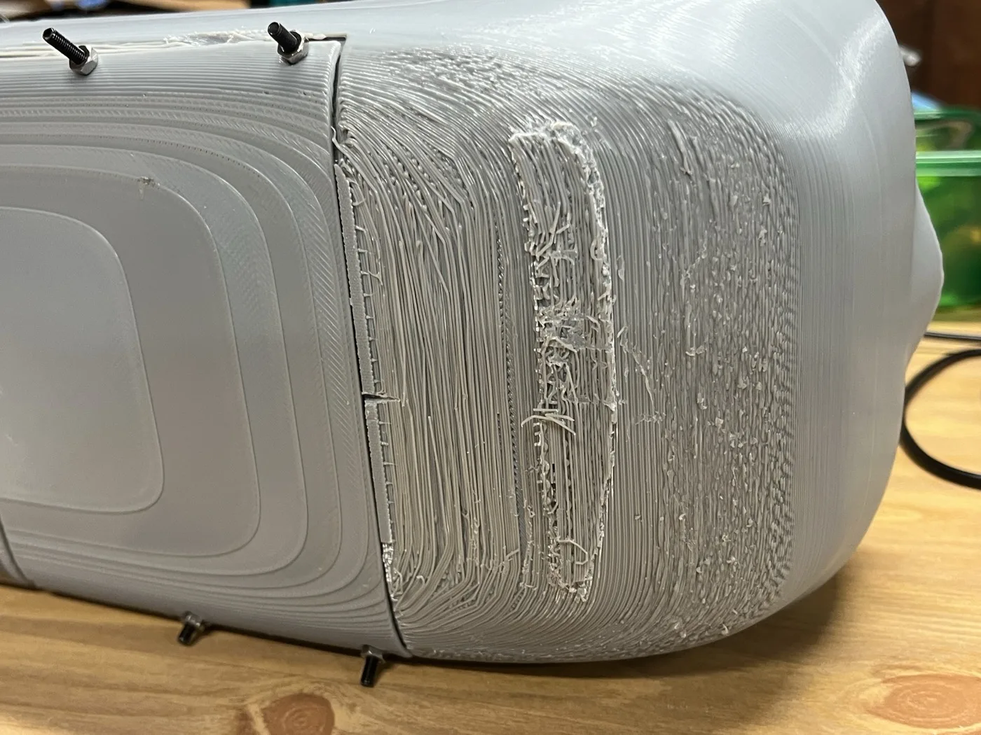
Both halves print standing on their rounded belly, on a raft with tree supports underneath. The supports were hard to get off, the same as on the front half, and the belly is rough where they were. Some of the remains are still on there. None of this affects how the body works, but it takes a while, and the surface isn't the smooth shape I designed.
Good enough for the first robot
All of this is usable. The body holds together, and nothing needs to be reprinted for the first robot. The list for the next version of the body is getting clear, though:
- Probably no battery door. A one-piece floor, with the battery and electronics loaded from the top.
- Screw seats on flat pads, set back from the edges, with slightly larger holes, since holes come out small on this printer.
- Move the lowest seam bolt up off the floor, and add something that locates the two halves before they are bolted.
- Change how the body stands on the print bed, so there is less support under the belly.
Log 16: Two CAN buses and two ways to fail (November 8, 2026)
A spare pair of CAN transceiver boards arrived in the mail today. I didn't need them, since the two I already had were enough, but they got me to finally run a test I had been putting off. The eight-motor robot will put its front legs on one CAN bus and its rear legs on a second one, with the Teensy driving both. Until tonight that was only a plan and a firmware sketch that had never been loaded onto hardware.
Double bus test
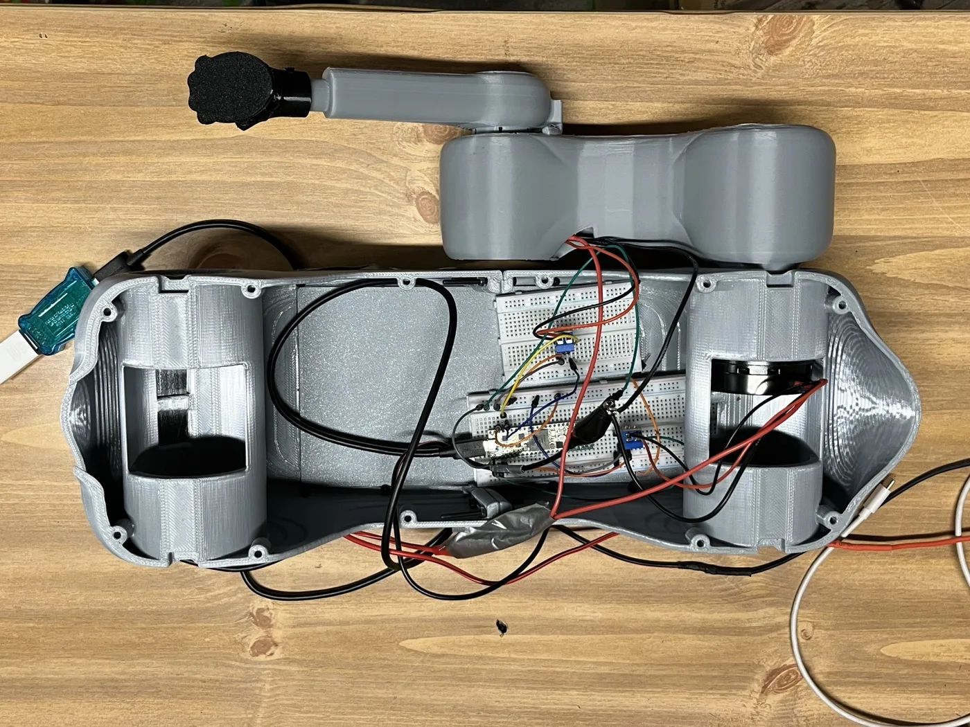
The leg's two motors normally share one cable. The knee gets its power and its CAN signal through the hip motor's second socket. To test two buses with only two motors, I unplugged that cable and gave the knee its own short pigtail, with power from the same supply and the CAN wires going to a second transceiver board on the Teensy's other CAN controller. Hip on bus A, knee on bus B. It took me a while to wire up, mostly because everything is still jumper wires on breadboards.
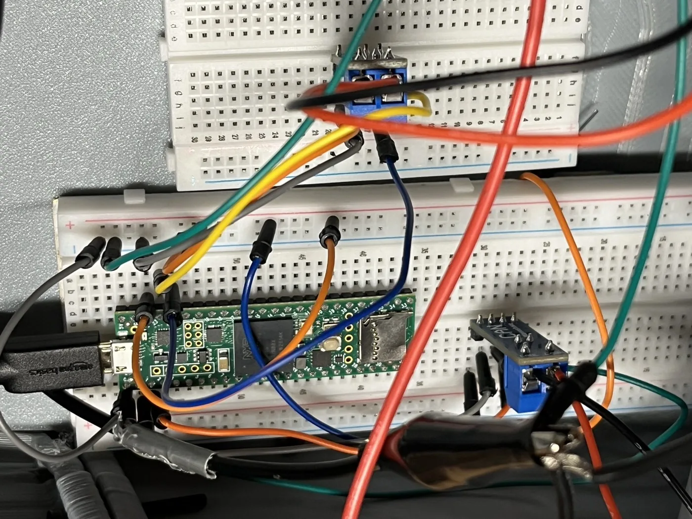
Then I flashed the new two-bus firmware for the first time. It scanned both buses and found the hip on A and the knee on B, with a note that the knee was not on its planned bus, which is exactly right for this bench setup. Both motors reported about 47.6 V, no faults, and the same current-loop gain I measured weeks ago.
Streaming test
The firmware has a test mode that enables the motors with all gains at zero, so they stay limp, and then sends one command frame to every motor on both buses at 500 Hz while counting every reply and every bus error. I ran it for a minute, then for ten. In the ten-minute run each bus carried 300,000 frames, every single one was answered, and both buses finished with zero errors. The motors warmed from 16 to 21 °C just sitting there enabled, and made a faint whine the whole time with nothing moving.
One number surprised me. The bench supply read about 0.12 A for the two enabled motors, which is around 60 mA each. The idle figure I had been using came from motors that were powered but not enabled, and it was about a quarter of that. So eight motors standing enabled will draw about half an amp before doing any work.
Two ways to fail
The part I actually wanted to see was the safety code. A simulation earlier in the project showed that if one leg's motor stops responding mid-jump and nothing notices for 20 ms, the robot falls without the firmware ever knowing. So the two-bus firmware tracks the age of every motor's last reply and aborts if any motor goes quiet for 10 ms, and it also aborts on any fault bit a motor reports. Neither path had ever been triggered on real hardware.
First test: with the frames streaming, I switched the 48 V supply off. The firmware stopped within the same tick on an under-voltage fault from the knee, ran its shutdown sequence into two buses that no longer had anyone to acknowledge the frames, printed its report, and came back to the prompt. When I switched the power back on, both motors answered a rescan with their faults cleared. No reset needed.
Second test: with the frames streaming again, I pulled one of the 3.3 V logic wires off the knee's transceiver board. The knee itself stayed powered and kept answering, but the Teensy could no longer hear it. The firmware stopped on "knee silent for 10 ms" after exactly five missed replies, which is the earliest it is allowed to trip. That bus had gone into the CAN bus-off state from the disconnected wire, and the next scan after plugging the wire back in cleared it on its own.
Takeaways
The two-bus plan works on real hardware, and both abort paths do what they were written to do. There is one test left in this series that I ran out of time for tonight: putting both motors on one bus with a single 60 Ω termination at the middle, which is how the robot's body will be wired, and streaming at 1 kHz for ten minutes to see whether that termination holds up. A circuit simulation this week suggested it might ring, so I want the real answer before eight motors are on the table.
Log 17: Kick speed, voltage limits and a runaway leg (November 10, 2026)
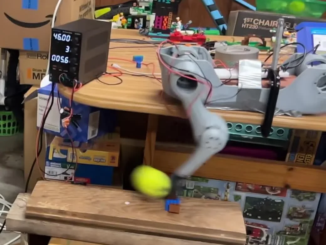
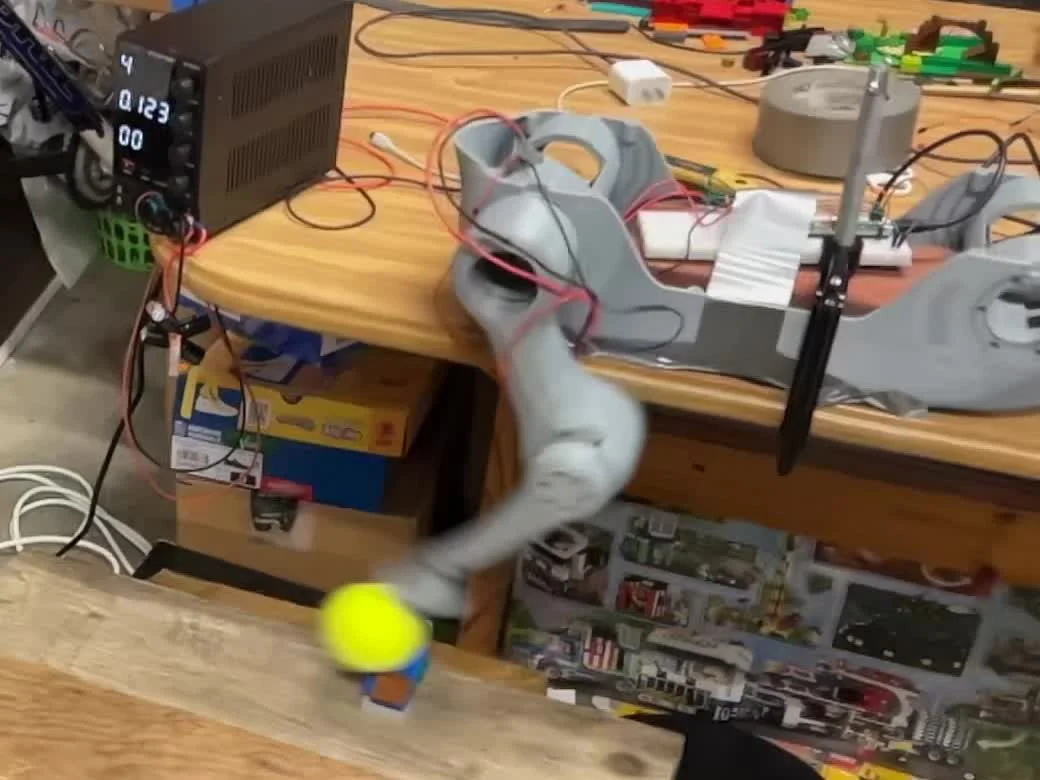
Yesterday the leg on the front of the printed body was kicking a tennis ball off a box. Today the goal was simple. Make the ball go faster. The first kick this morning sent it off at about 6.0 m/s (13 mph), and the best kick this evening reached 8.6 m/s (19 mph). On the way there, the leg spun all the way around once and ripped a wire, so a good part of the day went into safety code.
Measuring the ball
Every kick was filmed in 240 fps slow motion. A script finds the yellow ball in each frame and uses its known 67 mm (2.6 in) diameter as the scale. The change in its size shows how fast it moves away from the camera, so the speed counts all three directions. A fit of the ball's fall against gravity confirmed the frame rate. The camera moved a little between some kicks, so I treat differences under about 5% as noise.
The garage lights flicker at 120 Hz, which shows up as a strong pulse at 240 fps. It doesn't change the speed numbers, but every clip I use in a video now goes through a deflicker filter first.
A new kick shape
The kick is a whip kick. The hip swings forward while the knee snaps, and the timing between the two sets where the paw is fastest. With the old timing, the paw peaked well past the ball. I planned a new timing so the peak landed right at the ball.
The first kick with it quietly used the old timing anyway. The Teensy reads "0.20" as a hair under 0.2 and rejected it against its own lower limit, and the script on my computer never showed the reply. The script now checks every reply and refuses to kick if a setting wasn't accepted.
Once it ran, the new timing gave about 5% more ball speed at 6 m/s. At 8.5 m/s it gave none. The knee was still snapping when the paw reached the ball, and the ball pushed it back. Moving the ball forward to meet the paw at its fastest point was worse still. Out there the paw is already curving upward, so it hit the ball at an angle and the ball left at only 5.4 m/s.
The power supply limit
The bench supply had been limited to 4 A since the hop tests. The fastest kicks briefly ask for more than that, so I raised the limit to its maximum of 5.2 A. The same 8 m/s kick then sent the ball 10% faster, 7.2 m/s against 6.5. A 9 m/s kick that had stopped itself at 4 A also finished cleanly.
A bigger wind-up
The limits were originally configured such that the hip could only swing back about 67° from vertical. Holding the leg up by hand showed it goes well past horizontal with nothing in the way, so that limit was far too cautious. A longer wind-up gives the motors more swing to build speed over. The planning model said an 83° wind-up would add about 20% to the paw's speed at the ball for the same motor effort.
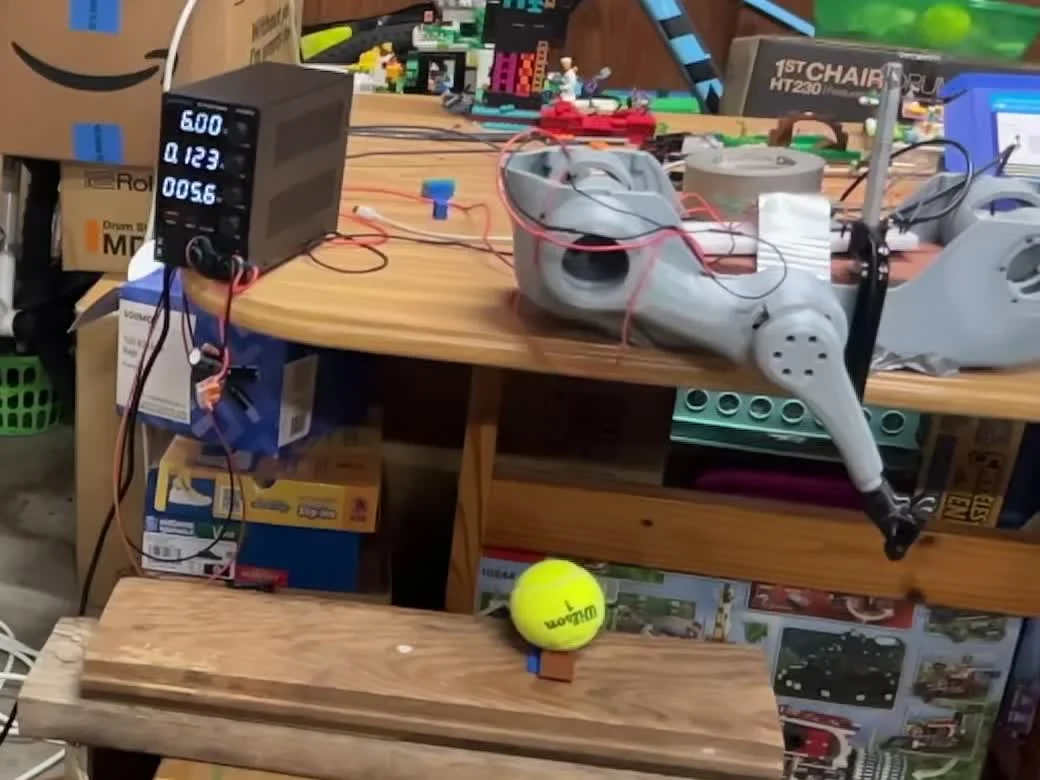
It worked. The kicks also tracked their plan better, because the hip had longer to get up to speed. A wind-up level with the hip (100°) gave no more speed, and it led to the problem below.
| Setup | Kick speed asked | Ball speed |
|---|---|---|
| Morning, old setup | 6.0 m/s | 6.0 m/s (13 mph) |
| Supply at 4 A | 8.0 m/s | 6.5 m/s (15 mph) |
| Supply at 5.2 A | 8.0 m/s | 7.2 m/s (16 mph) |
| 83° wind-up | 8.0 m/s | 7.6 m/s (17 mph) |
| 83° wind-up | 9.0 m/s | 8.0 m/s (18 mph) |
| 83° wind-up | 9.9 m/s | 8.6 to 8.8 m/s (19 to 20 mph) |
A runaway leg
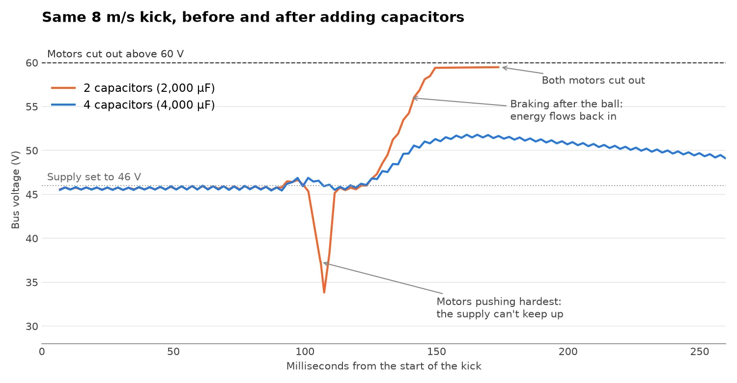
When a motor slows the leg down, it works as a generator and pushes current back into the 48 V line. This is called regenerative braking. A battery can soak that energy up, but my bench supply can't. Instead it piles up in the capacitors on the line and the voltage rises. The motors protect themselves by cutting out above 60 V.
I added voltage logging to the kick, and one kick showed the problem clearly. Braking after the swing pushed the line from 46 V to 59.6 V. On one run I didn't set up the ball in time, so the leg swung up and all the way around. The cables went with it, and one CAN-H wire ripped.
I repaired the wire and changed the firmware in three ways.
- The firmware itself refuses kicks above 9 m/s or wind-ups past 83°. Those limits keep the braking voltage under the 60 V cut-out. Once a regen clamp is fitted, I can send a command over USB to turn them off. That setting isn't saved, so the limits come back on every reboot.
- If a motor drops out mid-move, the firmware clears its fault and switches it back on every 3 ms, then damps the leg to a stop. Without the fault clear this didn't work, because an overvoltage cut-out stays latched until it is cleared.
- Every stop now lowers the leg slowly over about a second before switching the motors off, so a leg caught high doesn't drop and swing.
To test it, I had the firmware switch one motor off on purpose halfway through a slow move. It caught the leg within 50 ms for both the knee and the hip. The firmware can't brake a motor while that motor is still inside its own protection, though. A physical stop on the body and a proper regen clamp are the real fix.
More capacitors
The cheap fix for the voltage swing is more capacitance on the line. I already had two 1000 µF capacitors there and three spares from the same pack. I accidentally put in one of the spares backwards, with the "+" end into the ground. The supply held the voltage at about 9 V while that capacitor hissed and vented smoke, and I switched off. An electrolytic capacitor wired the wrong way acts almost like a short, so the stripe on its side has to face the negative wire every time.
With four capacitors in place, I ran the exact kick that had cut both motors out earlier. The peak dropped from 59.5 V to 51.8 V, and the dip while the motors pushed hardest almost disappeared.
A hard plastic paw
I thought the soft TPU paw might be soaking up part of each hit, so I printed the same paw in solid PLA. On the same kicks, the ball left at 5.5 m/s and 5.1 m/s, against 7.6 and 7.4 m/s with TPU. The ball's stand height had to change for the PLA paw, so this isn't a perfectly clean comparison. The knee also felt less push from the ball with PLA, which fits an off-center hit. Either way, the TPU paw went back on.
Still open
- On the best kick the line dipped to 28.8 V while the motors pushed hardest. The supply's 5.2 A can't feed that burst, so a battery is the next step for more speed. It will need the regen clamp from the RobStride Power Board I ordered.
- The CAN-H repair is taped, and it dropped out a few times later in the day. It needs solder, heat shrink and strain relief on both sides of the hip.
- The knee's screws worked loose during the day. They need threadlocker, or at least a check before every session.
- The thigh needs a physical stop well short of going over the top.