In the last week or so, I've made a good amount of progress on my custom robot dog. In this post, I want to give an update and talk about some things that I learned.
First of all, I have finally decided on the name of the robot. It's "LocksleyFox". You might wonder why it's a fox. It's kind of a long story, but I wanted to make something different from a lot of the other dogs out there, and frankly I haven't seen too many robots that are foxes. I think it would just be cute and interesting. So although it's going to be similar to a dog in terms of the four legs, I hope to eventually put a tail on there, and even some ears, and give it a fox image. Maybe even some fox-like tricks, whatever that means. But yeah, it's LocksleyFox. That's the official name. In future articles, instead of calling it My Dog, I'll probably just title it LocksleyFox.
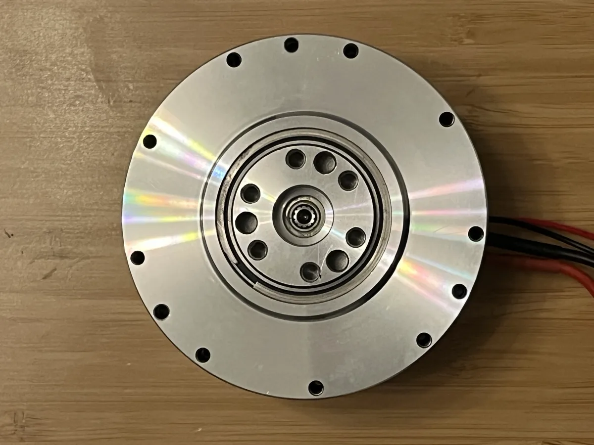
In terms of the actual hardware, I bought a few motors and a bunch of boards, tools and parts around a week ago. The general idea was I wanted to get one or more of these motors working. They also call them actuators, or you could even call them servos. It's this big metal disc that turns, and it's very precise about it. It has a certain speed and a certain location.
These are pretty high-end servos. They're the RobStride RS00, which is a smaller one, and the RS02, which is sort of a medium one. At one point I had bought an RS06, which is frankly just too big. I talked about that briefly last time. I ended up returning the 06 and experimenting with the 00 and the 02. Like I said, these are pretty powerful machines. They even tell you their current internal temperature. They have a lot of electronics built in, so I was really excited to get them working.
But it's not that easy, because there's some hardware required in between the motor and my MacBook Air, the laptop I'm using to do my basic testing and drive these motors. There's one board that I've been using, and tentatively plan on using on the actual LocksleyFox, called a Teensy. It's basically a driver board that has very fast response time, and it's able to control one or more motors.
The tricky thing is you can't plug a basic Teensy right into a motor (at least the cheap version I bought), because the protocol that's used is called CAN, C-A-N. So you need a separate, tiny board to bridge between the Teensy and the motor, or motors, because it can support more than one.
I had a few different boards that I tried with this. With the first one, I don't remember why it didn't work. I don't think I ever figured out the cause, but the motor just didn't move at all. So I moved on to a pack of three boards that I bought. They're pretty cheap, about $7, and each one has a few pins for just the necessary stuff: a ground, power, two control pins, and then the CAN H and the CAN L. Very simple. "CAN" stands for "controller area network" and is a special type of network for controlling motors.
The only problem is that to use it, you have to solder on a header, which is just a row of vertical pins, onto the board itself. The way it came, there were just six little circles, and they're smaller than the average header size. Pretty small. Not exactly surface mount, which I've done a long time ago and was extremely difficult, but nevertheless they were quite small, and the only way to get the connection working was to solder it.
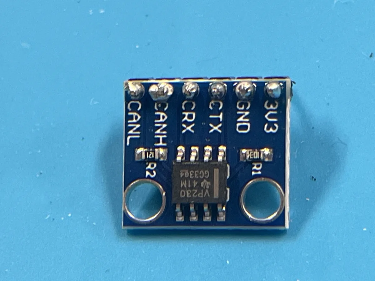
Now, keep in mind I do have a degree in electrical engineering, but I haven't used it at all in at least 20 years. So although I know the basics of soldering, I was quite rusty. I had a new soldering iron that I bought for this project, and it took me a while just to get that working, get it heating up, get the right cords, and then try to solder. I had some difficulties there, where the resultant connections didn't seem too solid. Maybe there were terminals unintentionally bridged together. To triage, I had to look at it through one of those magnifying glasses. I even considered buying a microscope designed just for that purpose, which could be between $150 and $200. I ended up not doing that, because the magnifying glass was good enough.
To make a long story short, I ended up soldering three of these boards. The reason I did three is the first one didn't work. Claude's idea was, well, maybe you have a short, or maybe you broke something. So I tried a second board, same problem, and a third board. After that, Claude finally realized that, hey, maybe there's a problem with the board, like a defect.
At first I was really doubting Claude, because Claude makes mistakes, you know? It's AI after all, and as I talked about in a previous post, mistakes are quite common in many domains, including when working with hardware. So I was really suspecting a Claude mistake, and I really pushed it to give me a root cause. I set it to the highest model, which is Fable at this time, and I said, I really need to know what's going on, because this is crazy.
It could have even been a software problem, because it's using software to drive it. It goes from my MacBook Air, to the isolator, to the Teensy, to the CAN board, to the motor. So there are a lot of steps there in the hardware, but there's also software behind the scenes that frankly I don't know much about. I know there's a protocol, and there's a special way that the MacBook Air communicates with the Teensy, and it goes from there. There were just a lot of points of failure.
After just a few minutes, Claude came back to me and said, you know what, there are a few forum posts from people with the same problem. And it's true, I checked them out, they exist. At that point, I was almost certain that it really was a bad board, especially considering the odds of three equally bad solder jobs were really low. It was $7 for three of them, which is quite cheap, and as a next step Claude recommended getting a more expensive one. I forget the exact price, but I think it was around $20 for two boards. They were pretty small, but the great thing about those boards is they didn't require any soldering. I was very thankful for that, with my eyes still a little bit sore from the previous soldering.
When this sort of thing happens with AI, you often say "Why didn't you tell me sooner!", but the nature of (current) AI models is that they just aren't that thorough.
The good news is, when I finally tried the first of those boards, it worked right away. I was definitely a little bit hesitant, worried about blowing something up (once I did see a huge spark) or that it wouldn't work, and it just worked. When I say worked, I mean my computer was able to communicate with the motor, Teensy, and CAN board. It told me everything was good, which was a first time for me. There's a bunch of readings I did with a multimeter to check the voltages and the resistance and all this stuff, and this time all those voltages were good. Before, it wasn't pulling them to the right value. I think they were stuck at zero instead of something like 1.5 volts.
So that was great, and then I actually asked it to move the motor, and lo and behold, it actually worked. Then about a day or two later, I got the second motor wired into the same circuit and that worked too. I even got them spinning at the same time!
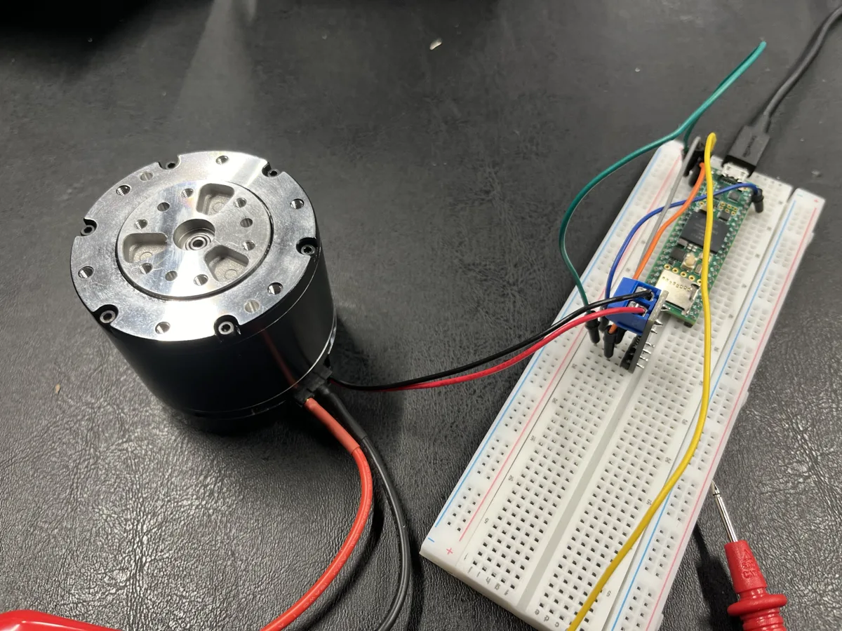
I recorded a short video, about 20 seconds, and I have it linked here in this article so you can see them moving. It's not that exciting, but it is proof from my end that I actually got these working.
For me, it was a really good achievement. Like I said, I haven't touched much hardware at the wire level in many years, so there are a lot of things to remember and a lot of things to learn. But wow, these are really beautiful motors. They're pretty heavy, but they're really shiny, and they look like something out of a science fiction movie. They're like works of art. I've done a good amount of research on other motors with similar torque, similar specs and similar weight, and these are the best ones by far that I've seen out there. There are some that are kind of similar, but these RobStrides are really the best. And I'm not trying to sell them. (I don't have affiliate links to them here.) They just seem like really good motors, so I'm happy that I got them working.
That's about it for this update. Keep in mind I'm purposely not giving you all the exact wiring diagrams and all the steps I'm doing. That would be quite lengthy. But once I get the whole dog...uh, fox working, I do have plans to eventually release this. Maybe it'll be open source. I'll figure out the licensing eventually. At that time, I'll hopefully have really clear diagrams, steps and instructions to build it yourself, but that's probably going to be at least a few months from now. If I am lucky.
I actually have some other things I'm working on in terms of the leg design, a few iterations, but I'll save that for another post, because it's going to be pretty involved. Thanks for listening, and thanks for reading.