In this post, I'd like to give an update on some things I've been doing, and also talk a bit about design considerations.
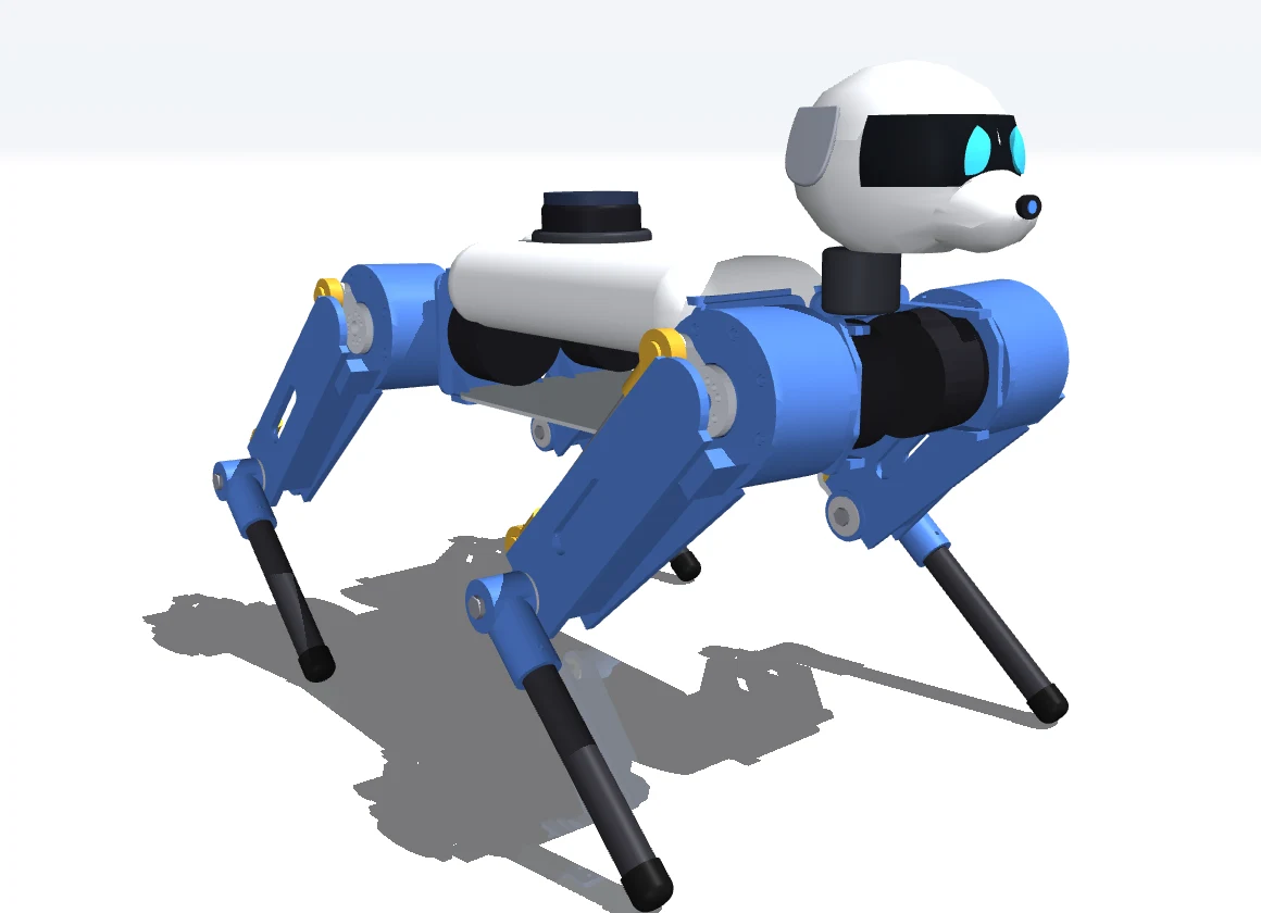
First, I want to announce that I've finally created a proper page for my robot on this website. It's just /locksleyfox, so you can follow that link to jump to it. There will be a few things on there, and one of them is a set of mini logs about specific experiments and tests I've run. Those will be a little like this blog. But they'll be less personal and more scientific, with fewer opinions and more hard data.
I'll try to include graphs and videos, and I'll keep adding to the page as I go. It's the one place where I gather all the information together, so you can find links to new updates there.
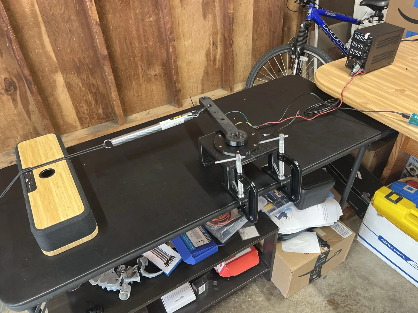
The second thing is that I created a YouTube channel. I actually linked a video from that channel in a previous blog post, but I didn't explicitly mention the channel itself. There are a bunch of videos on there now, over 10 so far. The majority of them are simulations, but I also have a few short live clips. For example, there's a problem I had with 3D printing, and a test I was running.
I plan to keep adding videos going forward, and I won't always link every one of them in a blog post or on the LocksleyFox page. Some I'll just post and see who finds them. So please take a look if you want to see what I've posted already, and of course, following the channel is always appreciated.
Now for the main topic of this article, which is design considerations. That's really one of the most fun parts of this project. It's a bit different from software. Software has design constraints too, but they're often more flexible. In the hardware world you have hard limits like heat, speed and weight, which are much harder to compromise on or ignore. In software you can often use tricks to work around those things more easily.
To give some concrete examples, I started by designing the leg. I'm still designing it, but I've reached a pretty good point where I'm going to start building it. I did go through a fair number of iterations, around five formal iterations, plus some other things in between. I want to talk about those iterations and some of the design choices I made.
Iteration zero: three motors per leg
The first iteration was really early, so I don't have a proper name for it. You could call it 0.9, or maybe iteration zero is a better name. This is where I started out with the idea of three motors per leg. Many quadrupeds out there have three motors on each leg, which makes 12 for the whole robot, or what they call 12 degrees of freedom (DOF). Each motor moves one joint back and forth, and that's one degree of freedom. So 12 seemed like a good idea, and even some of the smaller robot dogs you can get for $300 or $400 have 12 DOF. It seemed like an easy choice.
To explain what those are, the first DOF is the knee, the second is the hip, and the third moves side to side. The first two move the leg forward and backward, and the third moves it from left to right.
So I did a design with that, and it ended up being quite complicated and also quite expensive. Cost is another design consideration that applies even more to hardware than to software. There's the cost of each part, whether you send it away to be made or print it on a 3D printer. And many of the really critical parts, like the motors, you just have to order.
One of the motors I'm using is the RobStride RS00. It's a little hard to get. You can order it, but sometimes it's on back order and you have to wait a while, or only certain models are available. Still, it's definitely the best one I've seen so far.
There are a few different versions, but the RS00 is around $150. That may sound cheap, but multiply it by 12 and you get a pretty big number, and that's just for the motors. Add at least another few hundred dollars for the other parts, plus the computer, whatever I end up getting for that, and it's already a huge cost. Besides the motors there were the screws and nuts, though, and counting those it was about 130 parts per leg. That's a lot.
That design was expensive, but it was really versatile, since it can move along three different axes, and that's what a lot of the robots out there do. But I said to myself, this is the first robot like this I'm making, and I really want to prototype. I want to make what you'd call an MVP, a minimum viable product. That means something that works and actually walks. I'd really like it to flip, but that's more of a stretch goal (meaning nice to have but not needed).
So I thought about what I could cut, and the first thing was one of the motors, specifically the third, side-to-side one. Frankly, a lot of behaviors don't need it. You would need it to move sideways, like a crab walk, or for certain types of balancing. If the robot is pushed from the side, it can recover to a certain extent, but it's hard to balance properly without that third motor in the hip. Also, getting up from lying down would be hard without it.
However, basic things like walking, running, maybe standing on two legs, and even jumping (at least in a simulation) all work without it. There are robots out there, at least research robots like Minitaur and Stanford Doggo, with only two DOF per leg. That's eight DOF total, and they get a lot done.
Leg 1.0: two motors at the hip and a push rod
That was the first thing I cut, and that brings us to 1.0, which has two motors per leg. It still had a huge number of parts. The cost was going down, since there were fewer parts, but the trade-off is that heat now starts to become an important factor. In other words, how hot things get, which is important since if they get too hot they literally can start melting and malfunctioning.
The way I originally designed it, both motors were in the hip area. There were a few reasons for that. Some robots, like the Unitree Go2, which is one of my favorites, do that, and a bunch of others do as well. They use something called a push rod, which is a linkage between the hip and the knee. The whole point is that you don't have to put the motor in the knee itself, which makes the lower leg lighter.
There's also less heat to worry about, because the hip has a lot more area around it. A lot of this is based on simulations I've done as well, and it's a much cleaner design in terms of heat. We also took away one motor per leg, so it was getting cheaper. In many respects it was a nice design, and that's what we had for 1.0.
One of the problems I had with it is that it just looked odd. Having no motor at the knee looked somehow odd, and the push rod design seemed a little odd too. Frankly, it also added a lot of pieces and moving parts. It's not a huge cost, but the number of parts, the assembly work and the things that could break all go up with a push rod, compared to putting the motor in the knee.
Originally I said I wasn't going to put the motor in the knee. Keep in mind, a lot of this was going back and forth with Claude, getting feedback, looking at other robots and running simulations. Counting every screw, it was about 90 parts per leg, which is a pretty huge number. I really wanted to reduce that, because frankly I'm not that great at the mechanical building side, and I wanted to simplify.
Leg 1.0b: knee motor at the knee
So the next thing I did was put the knee motor directly in the knee instead of using the push rod. I ignored that option in the beginning because of the problems I mentioned, but I thought I'd try it out and run some simulations.
One thing I forgot to mention earlier is that I'm looking at two different RobStride motors, the RS00 as well as the RS02. The RS02 is a bit bigger, more powerful and more expensive, about $190 compared to around $150 for the RS00. In version 1.0, and even before that, I was planning to use the RS02 for the knee, up at the hip.
In 1.0b, I moved that motor to the knee, so it's still an RS02, what you could call a medium-sized motor. By the way, originally I had bought an RS06. It was a pretty huge thing, though, and just too big for what I need.
Moving the motor to the knee got rid of the push rod, and it looked better to me, a more balanced design. The problem is that there's now a lot more weight in the leg, and heat becomes a bigger problem, because there's a lot of movement at the knee. To be honest, I don't know all the physical reasons behind it. Some of this is stuff I've read online, things Claude told me or what I've seen in the simulations. But it turns out there's a lot of heat and force at the knee.
Leg 1.0c: the smaller RS00 at the knee
For the next iteration, 1.0c, I changed the knee motor to the RS00, the smaller one. Everything else is the same. The idea was to save money and make the leg lighter. A lighter leg reduces the total weight, which reduces forces in general. But the knee is still the focus point, and knee heat is still the weak point.
What I mean by that is if you run the robot a lot, for example at maximum speed for 10 minutes or so, the knee motor could just burn up. Obviously there would be protection, but that means the onboard computer would have to detect that it's overheating and stop, or slow down and take a break. That's possible too, but ideally I want it to follow me around the house, or maybe even walk around the city, who knows, without stopping every few minutes. So I do want to optimize for heat.
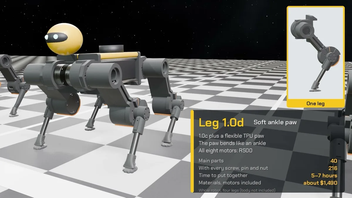
Leg 1.0d: a soft foot
Even though the heat was a problem, the inspiration for the next evolution actually came from a different angle. I showed the design to my wife, and she said the leg didn't look particularly nice. The bottom of the leg was basically like the bottom of a cane, a rubbery tip with no foot. She said I should really give it a foot. Being rubber, the tip wouldn't scrape things up, but it looked awkward, like the robot would hobble along.
So for 1.0d, I kept the RS00 at the knee and added a foot/ankle in place of the tip. I tried a few different options, like a bigger rubber stopper and different types of feet. Then, a bit to my surprise, I found that in simulations the foot actually reduced the force on the knee. That makes sense, because the foot itself is rubbery, so when it steps down, less force hits the knee directly. Less force on the knee means less heat, so the robot can perform movements longer.
Furthermore, the rubbery foot compresses when it steps down, and when the leg lifts back up, it springs back and returns a little energy to the system. That improves the efficiency of walking in general and uses a lot less power. Overall it's a win-win, and it's pretty easy to print. I've already printed a simple version. This design change gave a few gains, and it looks way better too. So that's 1.0d.
Leg 1.0e: fewer parts, all printed
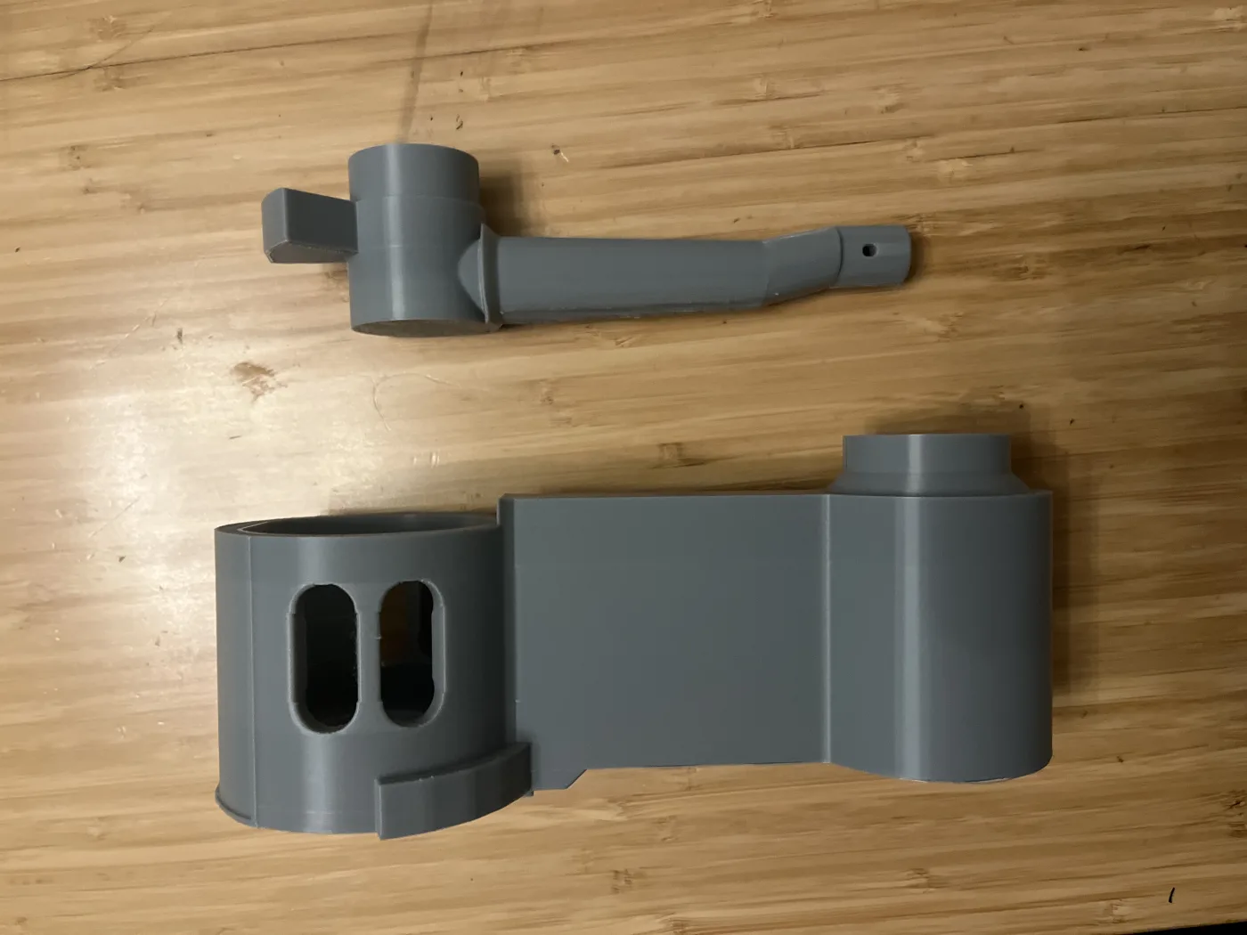
Finally, I looked at everything again and saw that there were still about 60 parts per leg, counting screws. So I went back to the drawing board and tried to optimize and take out pieces. For example, there used to be a hub and a carbon tube, and I replaced them with a one-piece printed shank. There are some other minor changes, like vents for heat.
The main idea was to reduce the number of parts. Some served a purpose but could be replaced by a single part, and some frankly weren't needed at all. That got it down to a much smaller number, about 50 parts per leg including screws, and only eight big pieces.
Originally, a few parts would have had to be ordered from outside because they needed to be extra strong. I ended up converting all the parts so that they can all be made on a 3D printer, except of course the motors, wires and such. That lets me print them in house without sending anything out. A 3D printer isn't cheap, but even for this project I'll make my money back by printing instead of ordering. For example, in one case it was about $80 to have a part made and about $30 to print it myself, and that's just one part. So you save a lot of money over time.
It's also much quicker. Of course I could wait for parts to get shipped in, but I'm really eager and want to build this as fast as I can. So it's really good to be able to print these parts. The point is that there are fewer parts, they're all printable in house on a 3D printer, and I can make them much faster.
All right, I know this post was a little rambling in terms of the different design considerations. Hopefully it was interesting, and it gives you a feel for some of the factors in designing a robot like this. I'm still in the relatively early stages, and hopefully I'll have more updates in the near future. Thanks for reading.
Videos and pictures